Simrad AP50 Autopilot
82 20221032B
VIOLET
BROWN
PINK
BLACK
RED
WHITE
WHITE
BLACK
RED
BLUE (GND)
YELLOW (+5V)
GREEN (WIPER)
NOTE 1
NOTE 2
9810
7
6
5
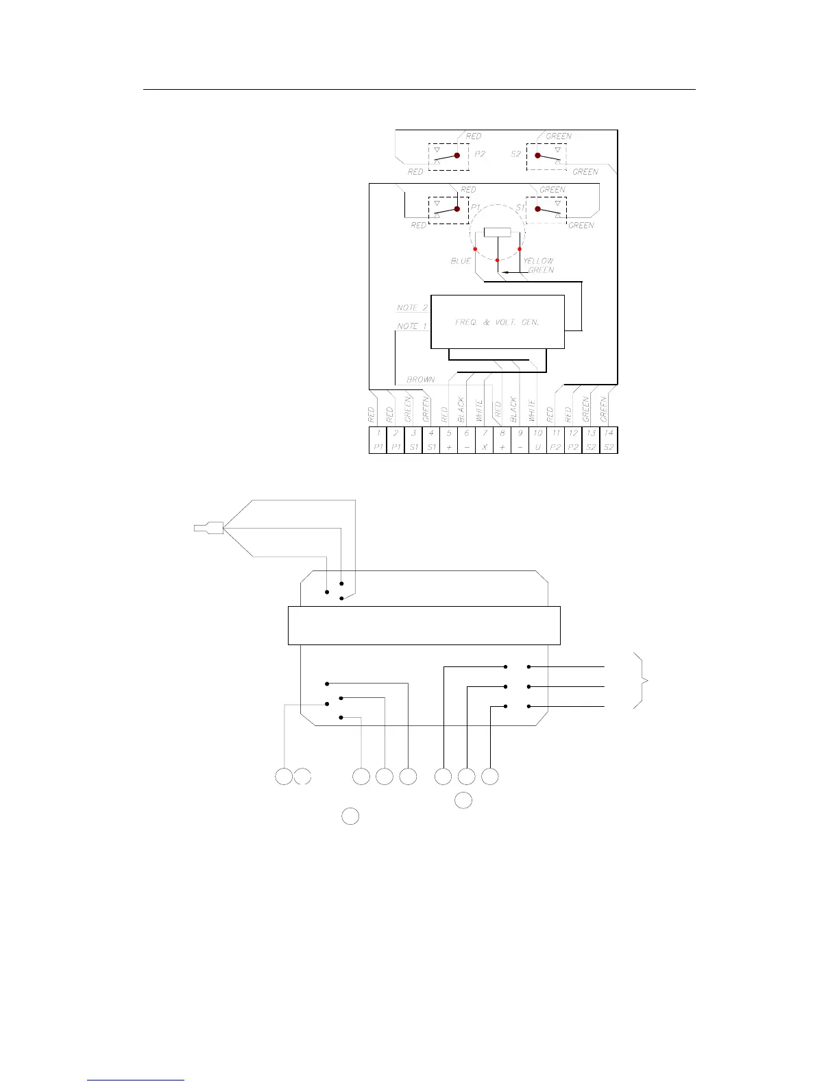
RF14XU ELECTRONIC MODULE
(VIEWED FROM BACK SIDE)
NOTE 1: Brown lead normally connected to .
Move to to invert the rudder indicator deflection.
NOTE 2: Normally connected for +/-45˚ rudder angle (violet, brown and pink leads are
not connected). For +/-60˚ connect brown lead to terminal 10, for +/-70˚ connect
pink lead to terminal 10, for +/-90˚ connect violet lead to terminal 10.
White lead must remain connected.
BROWN
8
9
8
9
TO
POT.
METER
Figure 4-9
RF14XU Internal wiring
Figure 4-10 shows how to connect the RF14XU Rudder
Feedback Unit to an AP50 system with 24V autopilot supply.