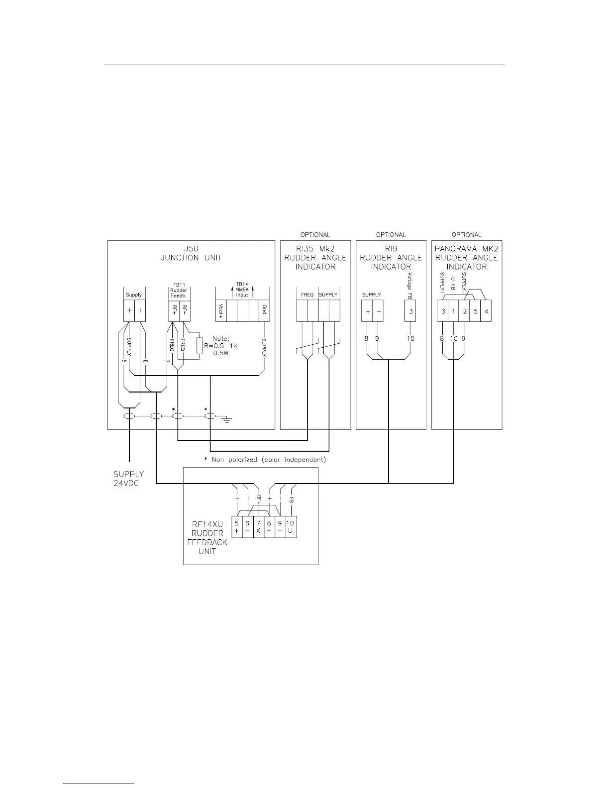
Installation
20221032B 83
The RI9 Rudder Angle Indicator is connected to the U-terminal
on RF14XU, while RI35 Mk2 Rudder Angle Indicator is
connected in parallel with the feedback signal for the junction
unit. Use the same supply for RI35 Mk2 as for the autopilot.
The connection shown below gives full functioning indicator(s)
also with the autopilot switched off. To have the indicator(s)
switched off with the autopilot, connect indicator(s) and rudder
feedback supply+ to J50 Vbat+ instead of J50 Supply+.
Note ! This configuration is only for 24VDC.
Figure 4-10 RF14XU connected to an AP50 system and
optional rudder angle indicators
Note ! The resistor R (0.5-1K, 0.5W) has to be mounted. The resistor is
not supplied by Simrad.