82 |
Wiring | GN70/MX610/MX612 Operator and Installation Manual
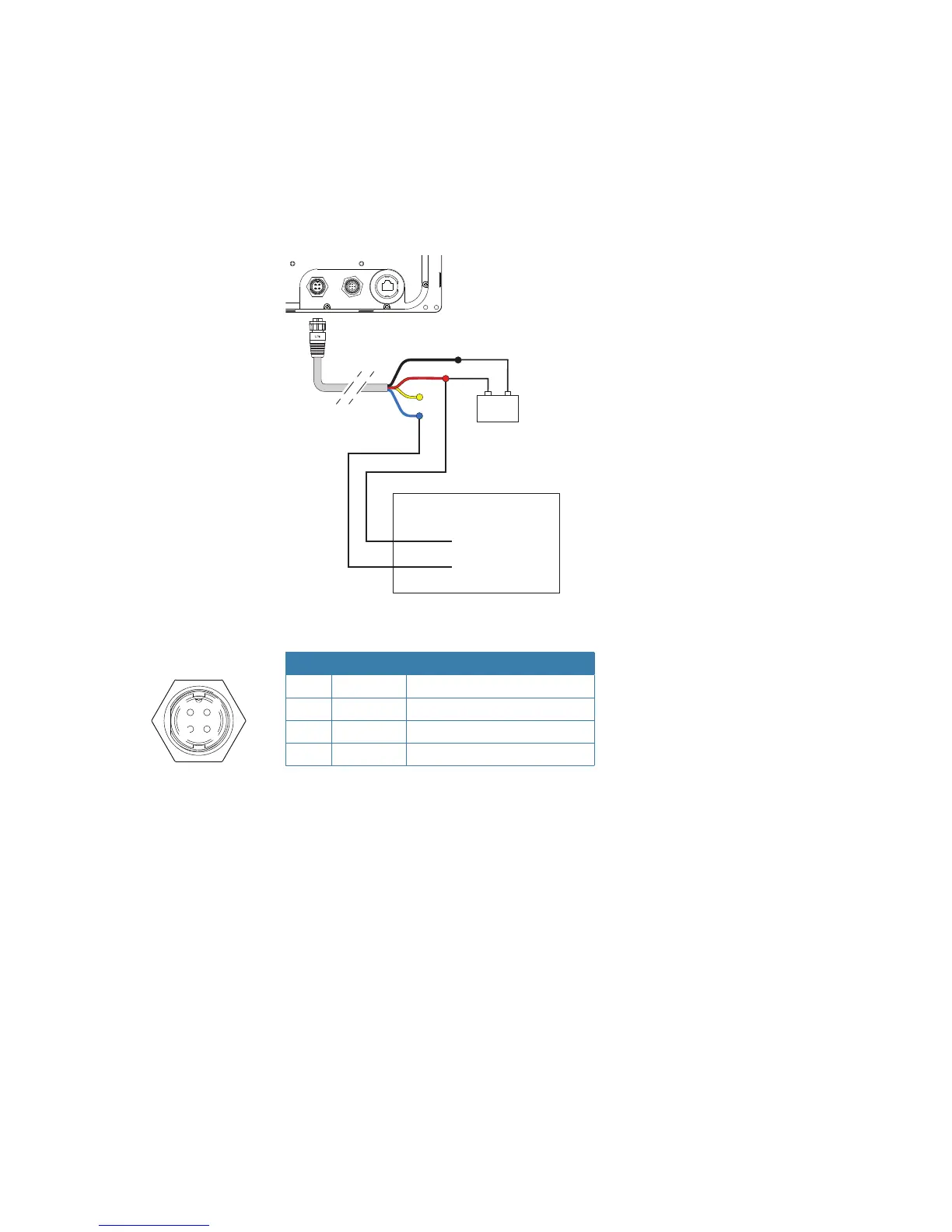
Central alarm panel with direct I/O interface
The interfacing described below applies for central alarm panels that use direct lines for alarm,
mute and acknowledge. For alarm panel using serial interface, refer to “IEC61162-1/2 (NMEA
0183) Devices” on page 79.
From the GN70/MX61x unit we are using the same two wires (red and blue) as for external
alarm relay connection.
Under normal operation you will see 12/24 V between these two wires. In an alarm situation,
or when power is lost, you will see no voltage.
12 - 24 V DC
+
_
CENTRAL ALARM PANEL
BATTERY+ (12 - 24 V DC)
ALARM
1
4
3
2
External alarm wiring Connection
Pin Color Description
1 Black Battery (-)
2 Blue External Alarm
3 Yellow External MOB
4 Red Battery (+), 12 - 24 V DC
1