| 75
Wiring | GN70/MX610/MX612 Operator and Installation Manual
Wiring
Wiring guidelines
The CAN network cables and other signal cables (i.e. antenna, compass, NMEA) should not be
run in parallel with other cables carrying radio frequency or high current, such as VHF and SSB
transmitters, battery chargers/generators, and winches.
Don’t make sharp bends in the cables, and avoid running cables in a way that allows water to
flow down into the connectors. If required, make drip and service loops.
If cables are shortened, lengthened or re-terminated, do insulate and protect all wiring
connections.
Most of the units are communicating on the CAN bus with drop cables. Try mounting the
units within the standard cable length supplied with each unit. Additional cables and cable
extensions are available from our distributors.
Warning: Before starting the installation, be sure to turn electrical power o. If
power is left on or turned on during the installation, re, electrical shock, or other seri-
ous injury may occur. Be sure that the voltage of the power supply is compatible with
the spec for the units!
GN70 or MX61x navigation system; basic wiring principles
The GN70/MX61x navigation system is comprised of the MX61x display unit, MX61xJB
junction box and MX521A smart D/GPS antenna unit. The MX61x display use CAN bus
backbone which makes it simple to interface to SimNet and other NMEA 2000 (N2K) devices.
The 12-Volt DC power to the CAN bus can be supplied through a T-Connector or by the
junction box.
NMEA 0183 devices such as the MX521A DGPS smart antenna, autopilots, radar and PC-based
ECDIS can be interfaced using the MX61xJB smart junction box.
In systems with the MX61xJB junction box the CAN bus is powered by the junction box. The
GN70/MX61x model have separate power supply cable and can be wired directly to 12-24
VDC. Other SimNet/NMEA devices are powered by the CAN bus.
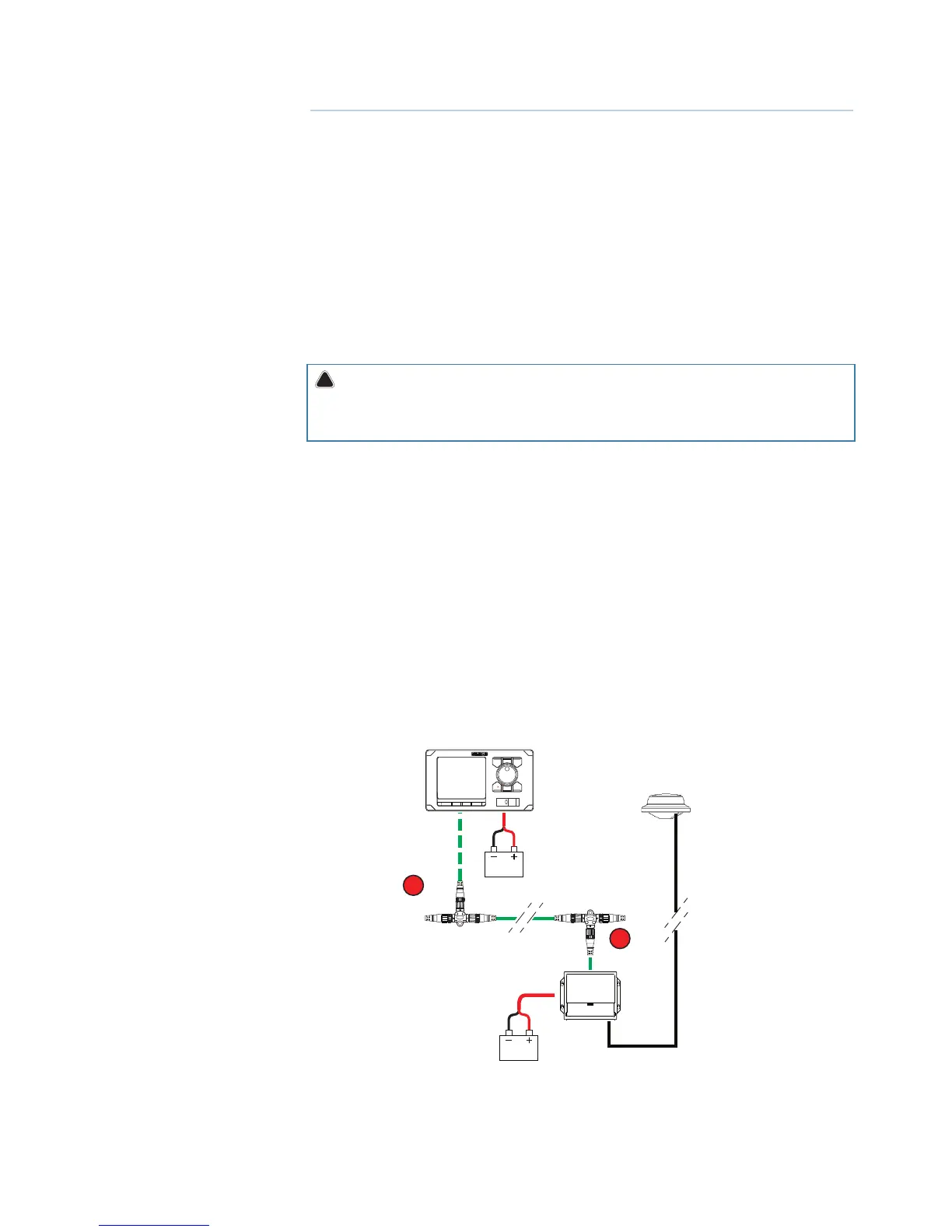
The following sections describe installation of the components listed in the illustration below.
Refer to separate manuals for detailed information about each interfacing unit.
T
12/24V DC
MX61xJB
12/24V DC
T
GN70/MX610/MX612
MX521
MX521A
MX521B
Port 3 & 4
MX61x with MX521 antenna and junction box wiring diagram
¼ Note: The MX521A/B antenna is connected to ports 3 and 4 of the junction box .
15