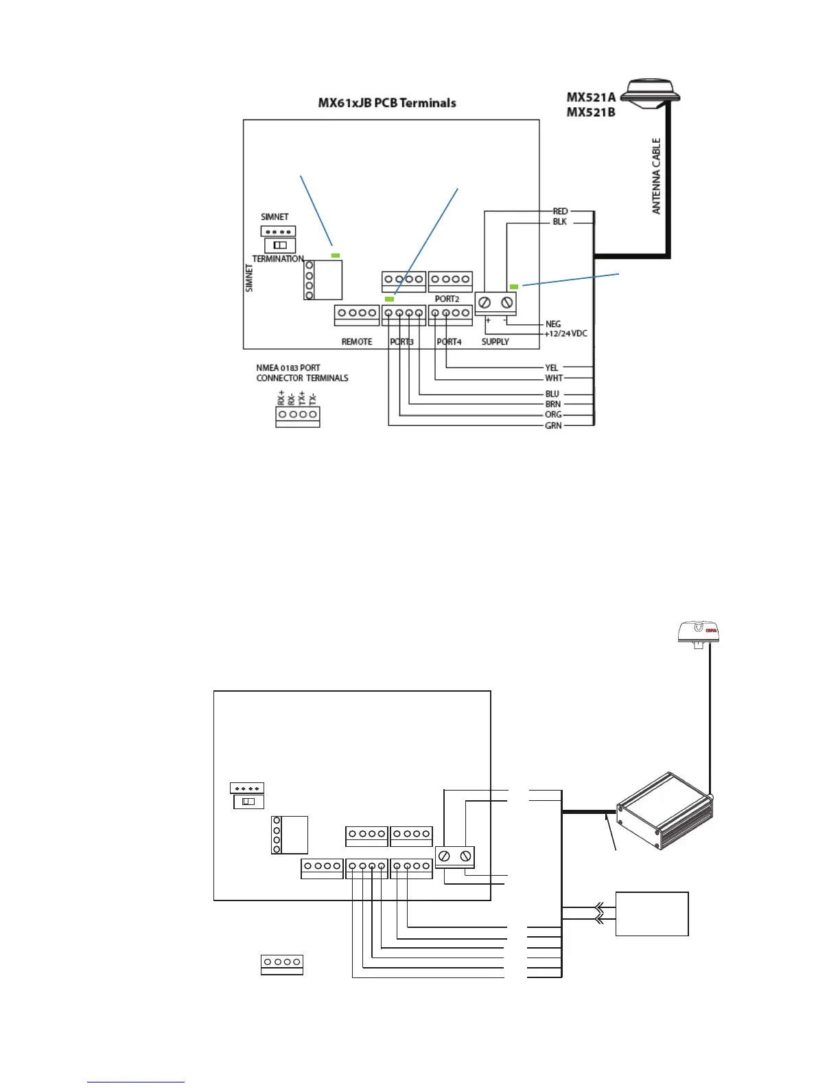
Normal operation
approx. 1 Hz flashing.
RX data, flashing
when receiving data
from antenna.
Supply before
fuse steady green.
MX521 to MX61xJB wiring Diagram
¼ Notes:
• Ports 3, 7 and 11 are high speed ports for antenna connection, defaults to 19,200 baud on
power cycle. Listener units connected must be set to operate at 19,200 baud.
• Ports 2, 6 and 10 are dedicated RTCM data input. Output is selectable.
• Antenna power leads are to be connected directly to supply:
Red wire to +
Black wire to -
REMOTE
PORT3
PORT1 PORT2
PORT4
SUPPLY
+ -
TERMINATION
SIMNET
SIMNET
BLU
BRN
ORG
GRN
YEL
WHT
RED
BLK
MX525A
MX61xJB PCB Terminals
3-Meter
Power/Data Cable
MXB5
COAX ANTENNA CABLE
RX+
RX-
TX+
TX-
NMEA 0183 PORT
CONNECTOR TERMINALS
+12-24 VDC
NEG
GRY
PRPL
Ext. RTCM
@4800 Baud
-
+
MX525A to MX61x JB wiring diagram