FMON10JEN 07.04.2017 Rev. 10J
20 (20)
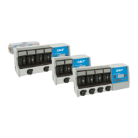
9 Operation
General
The measuring principle of the all Flowline monitor flow meters are to measure the rotation times of a sensitive
lightweight turbine. A special inductive proximity switches in the flow meter senses the metal-coated wings of
the turbine.
The control unit in the monitor reads the rotation times of the turbines from the flow meters and calculates the
actual flow rate using a pre-programmed formula. The set viscosity grade and measured current temperature
are used as parameters in calculation for best accuracy.
The flow meters communicate with the control unit using a bidirectional bus. The control unit reads rotation
information from the flow meters and writes LED status to the flow meters according to calculated flow.
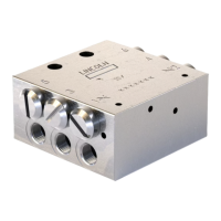
In FL50 the oil flows through two parallel flow tubes: main flow tube and side flow tube. Only the flow in side
flow tube is measured. The side flow measuring result and main flow are converted to total flow rate in the
control unit software. The side flow to be measured is separated from the main flow with an adjusting valve.
The adjusting valve affects main flow and side flow synchronically.
In FL100 the oil flows through four parallel flow tubes: two main flow tubes and two side flow tube. Only the
flows in side flow tubes are measured. These two side flow measuring results and two main flows are
summed in the control unit software to generate the total flow
The monitor includes parameters for controlling the flow rate measurements. There are parameters that are
individual for each flow meter (e.g. alarm limits) and parameters that are common for all flow meters in the
monitor (e.g. oil viscosity grade). The parameters are set by the user’s interface in the control unit. Refer to
section 8.6.
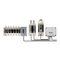
A common alarm relay output is included in all monitors. If more versatile alarm outputs or communication are
required, an optional plug-in CAN, Relay-CAN and mA-output modules are available.
The Relay-CAN module enables several alternatives for alarms, for example a separate alarm from each flow
meter and several common alarm categories: low, high, pre-alarms and zero flow alarm. It and also CAN-
module includes CAN-bus communication for remote monitoring of flow meters by the customer’s process
control system or by SKF Flowline software. Communication adapters from CAN-bus to several field buses
like Profibus and Modbus are available. An optional analog mA-output module provides an analog interface,
which is flexible to connect with other process equipment.
All Flowline monitors include a serial port for communicating with a PC. An optional SKF Flowline software is
available which can be used for setting the measuring parameters and for monitoring the flows instead of the
local user’s interface.