FMON10JEN 07.04.2017 Rev. 10J
35 (35)
Electrical connections
The terminals for external electrical connections locate in the control unit. The group electronics board is
equipped with plug-in screw connectors for the electrical cables.
Connections within monitor between flow meters and control unit are performed through a motherboard. Con-
trol unit is connected to the motherboard with a flat cable. Flow meters are connected to motherboard as plug-
in units.
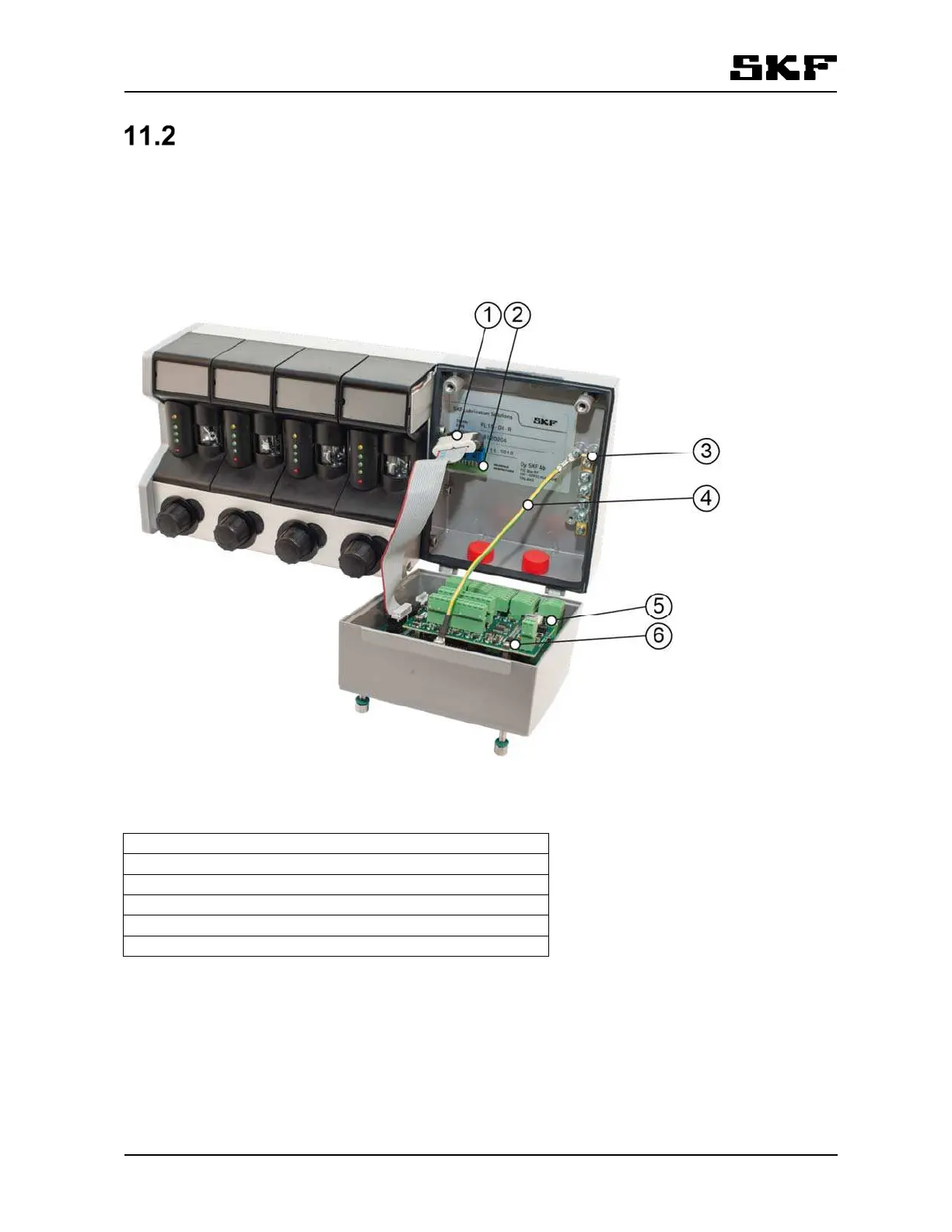
The figures below illustrate locations of the components in the control unit. ( Figure 12). The figures also
show the cover opened as during normal maintenance operation.
Figure 12 Control unit connections
1. Flat cable
2. Motherboard
3. TE-bar, for connecting the shield of the CAN cable
4. Grounding wire, for grounding the cover of the display unit
5. Group electronics
6. Optional interface modules (mA, Relay-CAN and CAN)