FMON10JEN 07.04.2017 Rev. 10J
43 (43)
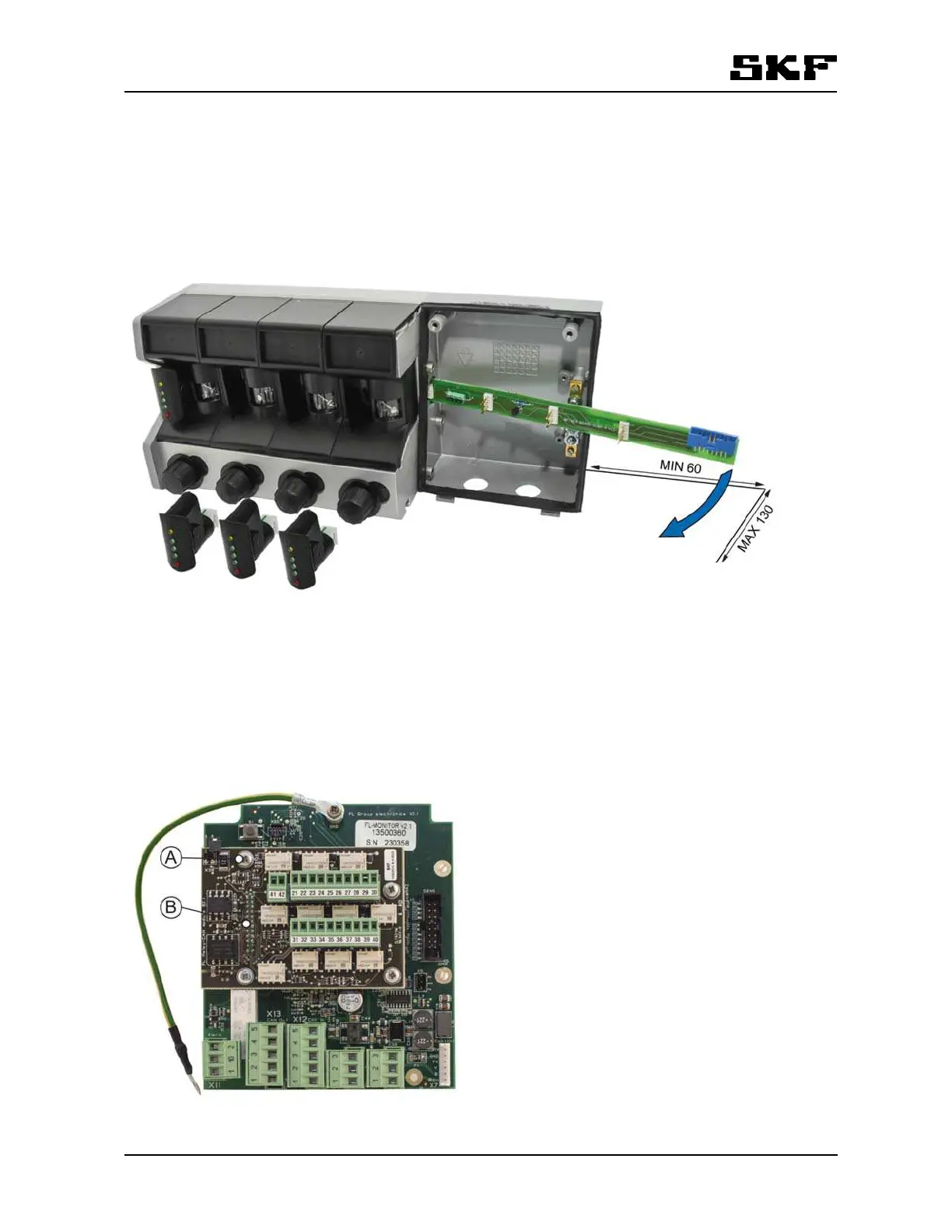
12.1.5 Removing and reinstalling motherboard
Remove all sensors and the flat cable before removing the motherboard.
Pull motherboard out of its slot as far as you can and maneuver it gently out of its position by twisting it slight-
ly.
The maximal twist angle is 60°. See the figure below.
Reinstall the motherboard by repeating the above steps in reverse order.
Figure 18 Removing motherboard
Spare parts: FL-Motherboard (Refer to section 16 Spare parts).
12.1.6 Installing optional Relay-CAN, mA-output or CAN module
Remove the four screws (A) for the add-on board from Group electronics. If there is a plastic shield fixed with
those screws, remove it. The shield cannot be used with the add-on board.
There is a 22 pin connector (B) on the left side of Relay-CAN, mA-output or CAN module.
Be careful to plug in the connector pins to the female connector (X18) on the Group electronics board.
Figure 19 Attach the four fixing screws (A) to install the optional module.