FMON10JEN 07.04.2017 Rev. 10J
41 (41)
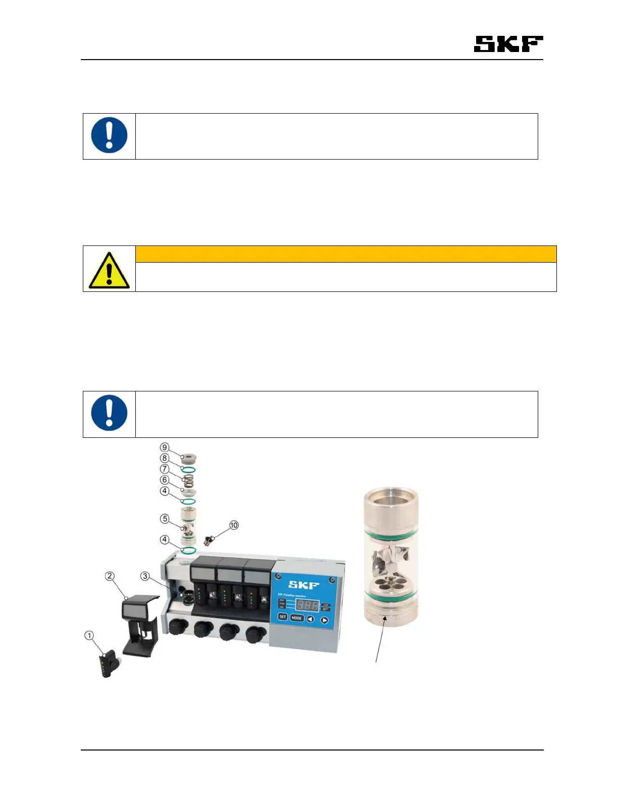
12.1.3 Removing and reinstalling flow tube assembly
Close all flow valves while replacing a flow tube assembly
Remove flow tube assembly according to following instructions (numbers refer to part numbers in Figure 16).
1 Remove sensor. (part 1)
2 Remove flowmeter cover. (part 2)
3 Open hexagonal plug. (part 9)
WARNING
Make sure that the spring (pos.7) that applies force to the turbine mechanics does not fling the
parts loose.
4 Remove spring, upper flange and O-ring from the drillings of the monitor body. (parts 6,7,8)
5 Remove flow tube assembly and O-ring. (parts 4,5)
6 Remove laminator. (part 3)
7 Double check the condition of non-return valve. It is locating in outlet connection of flow meter (part 10)
Replace required parts and reinstall the flow tube assembly in reverse order.
Make sure that the visible groove in the flow tube is at the lower end of the tube (see arrow in
the figure 16 .
Figure 16 Replacing a flowtube assembly and visible groove
Spare parts: FL15-KIT-FLOWTUBE-A 13120472, FL50-KIT-FLOWTUBE-A 13120477 and FL NON-RETURN
VALVE 13771880 (Refer to section 16 Spare parts).