FMON10JEN 07.04.2017 Rev. 10J
53 (53)
protocol CAN2.0A
bit rate 50kb/s
14.2.1 CAN bus connectors
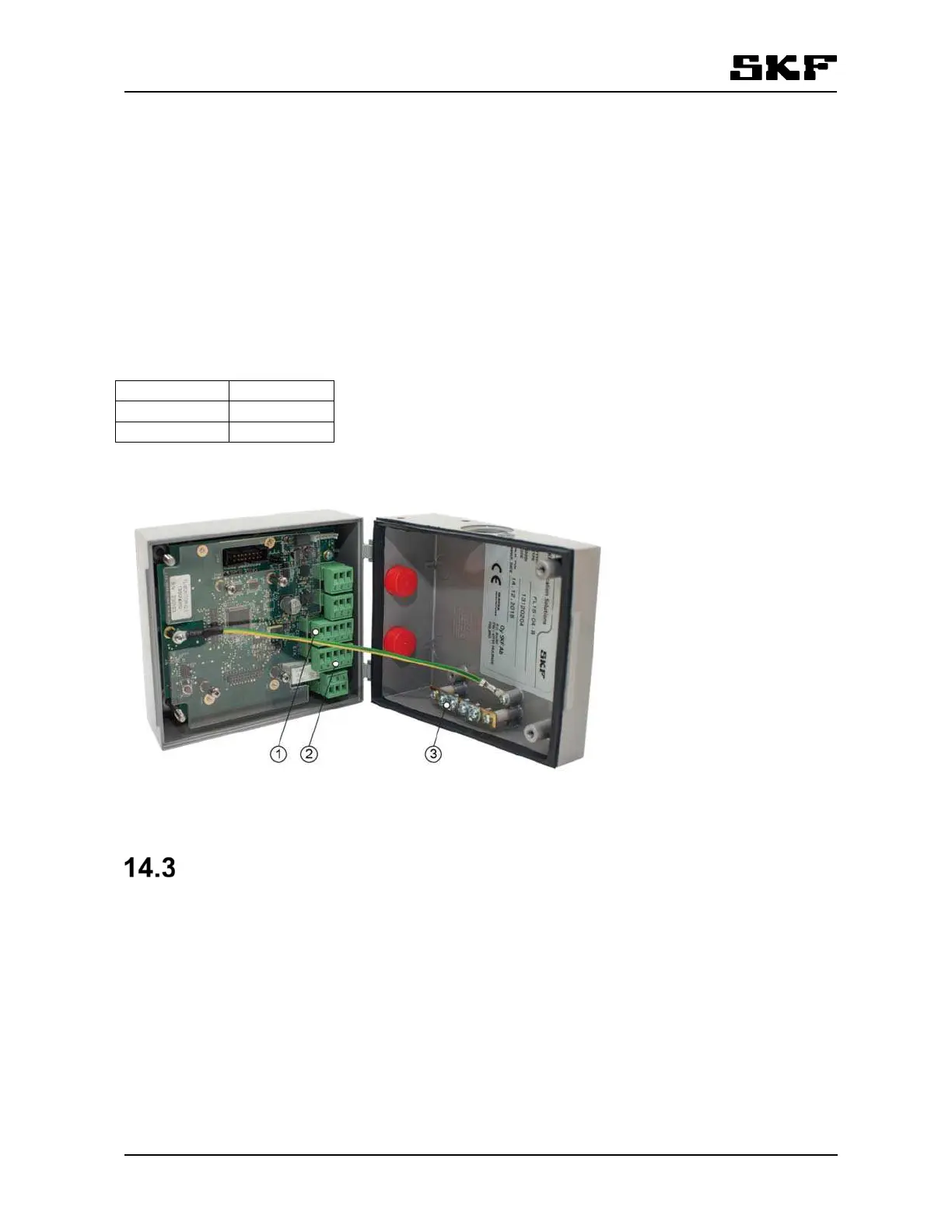
In Flowline monitor CAN bus screw terminals locate in connectors X12 and X13.
The connectors are connected in parallel for chaining the bus from one monitor to the next one.
X12 is marked CAN In and X13 is marked CAN Out but electrically they are connected parallel and are equal.
Table 18 Bus connectors
TE-bar is for connecting the cable shields.
Figure 22 Connectors for CAN bus in monitor, 1: X12, 2: X13, 3: TE-Bar
mA-output module
FL mA module is a plug-in interface board for SKF Flowline monitor. It has ten channels of flow rate depend-
ent, scalable, 4- 20 mA analog output for each flowmeter in the monitor.
The module is compatible with Flowline monitor models FL-15, FL-50 and FL-100.
The FL mA module is installed in the optional board slot of the FL Group electronics.
X12, X13:1 CAN_GND
X12, X13:2 CAN_L
X12, X13:3 CAN_H