FMON10JEN 07.04.2017 Rev. 10J
24 (24)
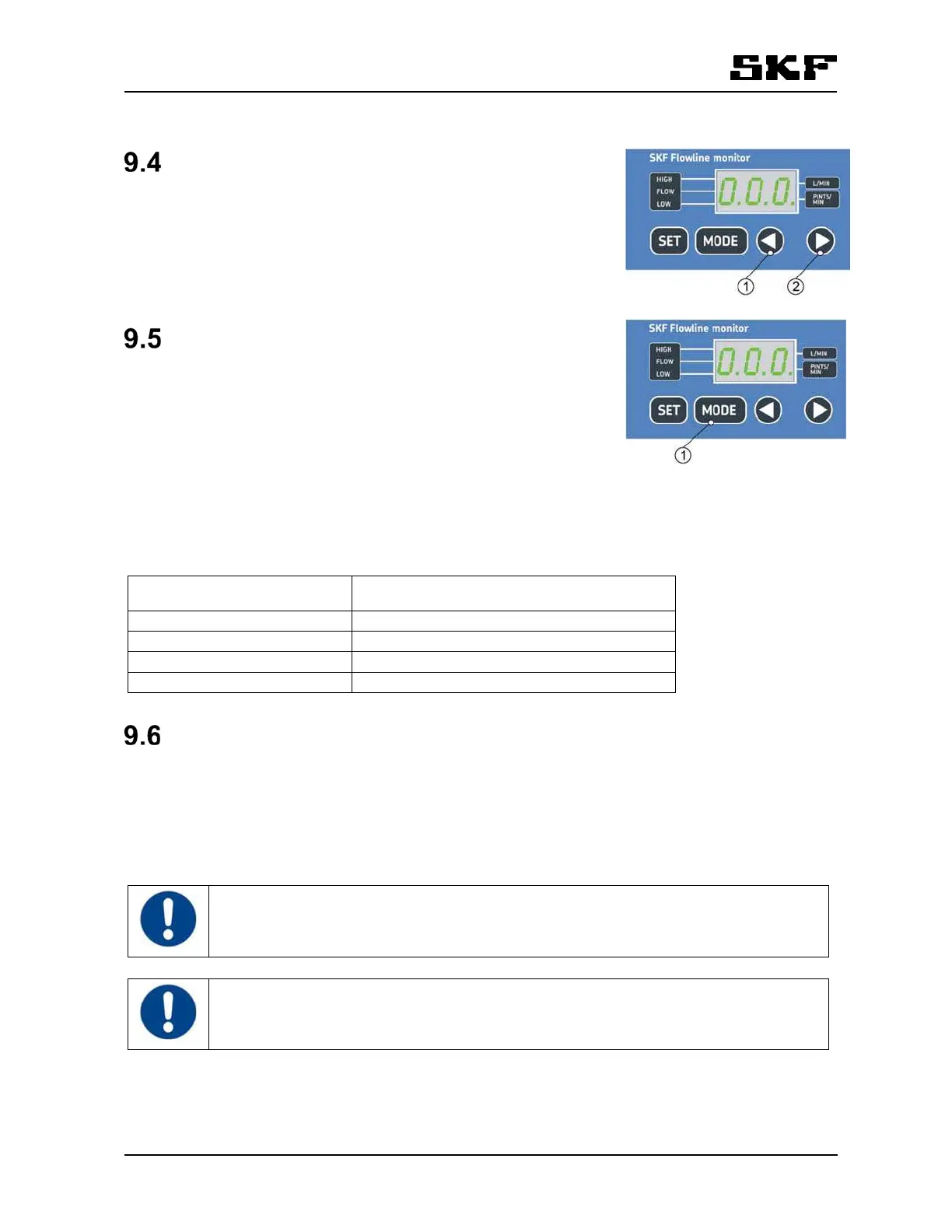
Selecting a flow meter
Press the arrow keys to toggle between flow meters. Flow meter number
is displayed in the control unit (e.g. "F2" = flow meter in position 2) and a
LED is blinking in the flow meter that is selected on the display. After the
last flow meter, oil temperature is displayed.
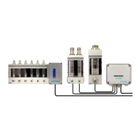
Selecting display mode
Press MODE-key to toggle between different display modes in the follow-
ing order:
1. FLOW - flow rate
2. LOW - low flow alarm limit
3. HIGH - high flow alarm limit
Nominal flow rate settings can be displayed by pressing the SET-key mo-
mentarily in mode FLOW. The display returns to mode FLOW after 5 seconds.
The resolution of displayed flow rate depends on the current flow ( table 6).
Table 6 Display resolution for flow rate
Flow rate (l/min or pints/min) Display resolution (l/min or pints/min)
0…0,5 0,01
0,5…2,0 0,05
2,0…20,0 0,1
20,0…100,0 0,5
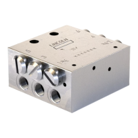
Flow rate adjustment
9.6.1 FL15 and FL50 flow meter adjustment
Oil flow rate is adjusted individually for each lubrication point. Flow valves are located in flow meters
( fig. 1). The flow rate decreases when the flow valve knob is turned clockwise. The flow rate increases
when the flow valve knob is turned counterclockwise.
Select the flow meter to be adjusted on display, then real flow could be monitored and the
update rate of the flow meter LEDs is higher.
With low flow rates, there is a slight delay in displaying the flow rate values. The flow rate is
updated on display only when the turbine wing goes past the sensor.