FMON10JEN 07.04.2017 Rev. 10J
25 (25)
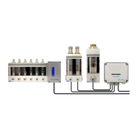
9.6.2 FL100 flow meter adjustment
The oil flow rate is adjusted with two separated flow valves, which are located in flow meter ( fig. 4). The
flow rate decreases when the flow valve knob is turned clockwise. The flow rate increases when the flow valve
knob is turned counterclockwise.
The total flow in the FL100 is a sum of two flows FA and Fb. These flows can be monitored separately by
pressing the arrow keys and switching the display between FA, Fb and the sum flow F. The individual flows
FA and Fb should be adjusted to be close to half of the sum flow.
Start-up sequence
When the power is switched on, monitor starts with the startup sequence. All display segments LEDs are on,
display unit and display mode LEDs are flashing. Flow meter LEDs are switched on in turns. The startup se-
quence takes 5-10 seconds. In the end of the sequence the CAN bus ID (e.g. 1) and the software version
code of the control unit is displayed (e.g. code 3.11).
After start-up, flow meter LEDs indicate the current flow rates and the flow rate of the first flow meter is dis-
played in the user’s interface.