FMON10JEN 07.04.2017 Rev. 10J
36 (36)
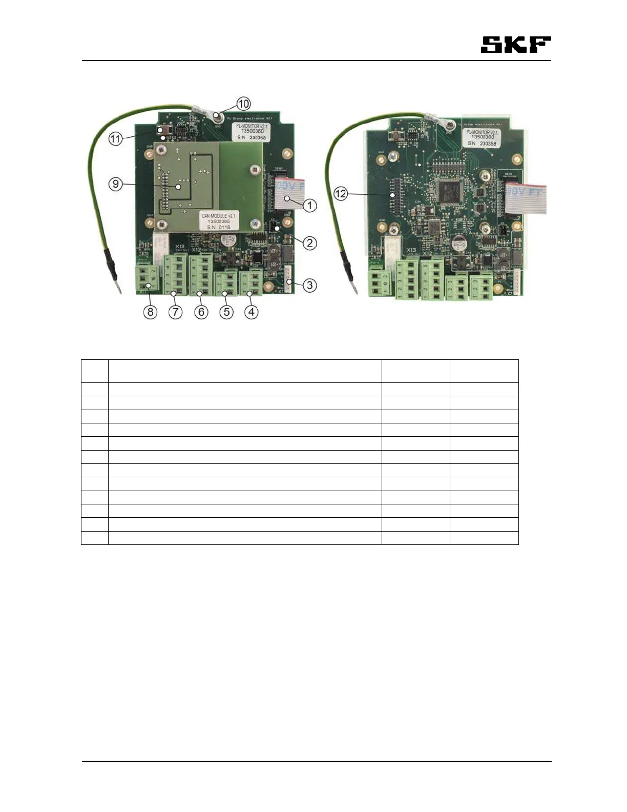
Figure 13 Group electronics connections
Nro Description Connector Type
1. Flat cable, flow sensor connection X5 Sens
2. RS232 port connector for a local PC X6
3. Auxiliary connector for special applications X7 Control
4. 24V AC/DC power supply connector(in) X9 PWR in
5. 24V AC/DC power supply connector (out to next monitor) X10 PWR out
6. CAN cable connector (in) X12 CAN in
7. CAN cable connector (out) X13 CAN out
8. Alarm output connector X11 Alarm
9. Optional Relay-CAN module, mA-module or CAN-module. screw
10. Grounding wire, for grounding the cover of the display unit screw
11. Button for firmware update S1
12. Connector for optional modules X18