FMON10JEN 07.04.2017 Rev. 10J
37 (37)
Table 10 Electrical connections
Connector Description Terminals
24V AC/DC power supply
connector Pwr In
24 VDC (20...36VDC) or
24 VAC (-20...+5%).
Monitor power consumption: 5 W.
Fuse: Resettable polymer fuse 750mA
X9: 1 Frame ground,
do not connect
X9: 2 AC or –DC
X9: 3 AC or +DC
24V AC/DC power supply
connector
(out to next monitor)
Pwr out
Monitor power supply chaining option. X10:1
Internally
connected to
X9: 1
X10:2
Internally
connected to
X9: 2
X10:3
Internally
connected to
X9: 3
Alarm output connector
Potential-free connection for connecting
monitor alarms to process control sys-
tem. Alarm is active, when one or more
flow meters are in alarm mode or if the
system has detected a defective flow
meter.
Contact open in alarm mode and when
monitor is not powered.
Max load:
30 VDC/1A, 120VAC/1A, resistive load
X11: 1
Alarm output
X11: 2 Alarm output
X11: 10 Not connected
CAN cable connector
X12, CAN In,
X13, CAN Out
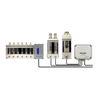
Interface for SKF Flowline Hub or
process control system
CAN 2.0A (Control Area Network)
data transfer protocol.
Requires optional CAN or Relay CAN
module.
See also SKF Flowline monitor CAN
interface manual.
X12,X13: 1
CAN GND
X12,X13: 2 CAN LO
X12,X13: 3 CAN HI
X12,X13: 4-5 Not connected
Auxiliary connector
Used only in special applications X7
RS232 port connector for a
local PC
RS232-compliant connection.
Local connection to PC with
SKF Flowline Software.
Data transfer distance: max. 10 m.
A cable with D9 connector, length 10 m,
is available (SKF code 13772010).
X6
Relay-CAN module (option)
Versatile Relay and CAN-bus communi-
cation interface board for Flowline moni-
tor
See paragraph 13.1 & 13.2
CAN module (option)
CAN-bus communication interface board
for Flowline monitor
See paragraph 13.2
mA-output module (option)
Analog output interface board for Flow-
line monitor
See paragraph 13.3