21
6
4
5
3
7
9
8
10
11
13
15
17
12
14
16
18
1920
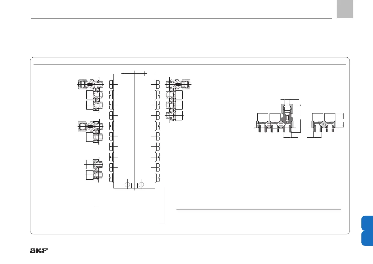
Progressive metering device inlet
Crossporting
3-bridge, with one
outlet and check valve
M10x1 = VPBM-C3
G1/8” = VPBG-C3
Crossporting
2-bridge, without
outlet port
without check valve
M10x1 = VPBM-C-S2
G1/8” = VPBG-C-S2
Crossporting
4-bridge, with one outlet
port and check valve
M10x1 = VPBM-C4
G1/8” = VPBG-C4
Crossporting
2-bridge, with one
outlet port and check
valve
M10x1 = VPBM-C2
G1/8” = VPBG-C2
~29
18
for pipe Ø6 mm
Thread
M10×1 taper/G
1
/
8
VPBM-C3 VPBM-C-S2
Connection fitting for cross-porting adjacent outlets
Number of
outlets to be
crossported
Order No. of complete
connection fitting, including banjo
bolts and fittings for
pipe Ø 6 mm and check valve
Order No. of complete
connection fitting
without fitting
M10×1 G1/8 M10x1 G1/8
2 VPBM-C2 VPBG-C2
VPBM-C-S2* VPBG-C-S2*
3 VPBM-C3 VPBG-C3 – –
4 VPBM-C4 VPBG-C4 – –
Bridge, installation position left
Bridge, installation position right
- 117 -
951-230-008-EN
Version 04
EN
 Loading...