6. Assembly
6
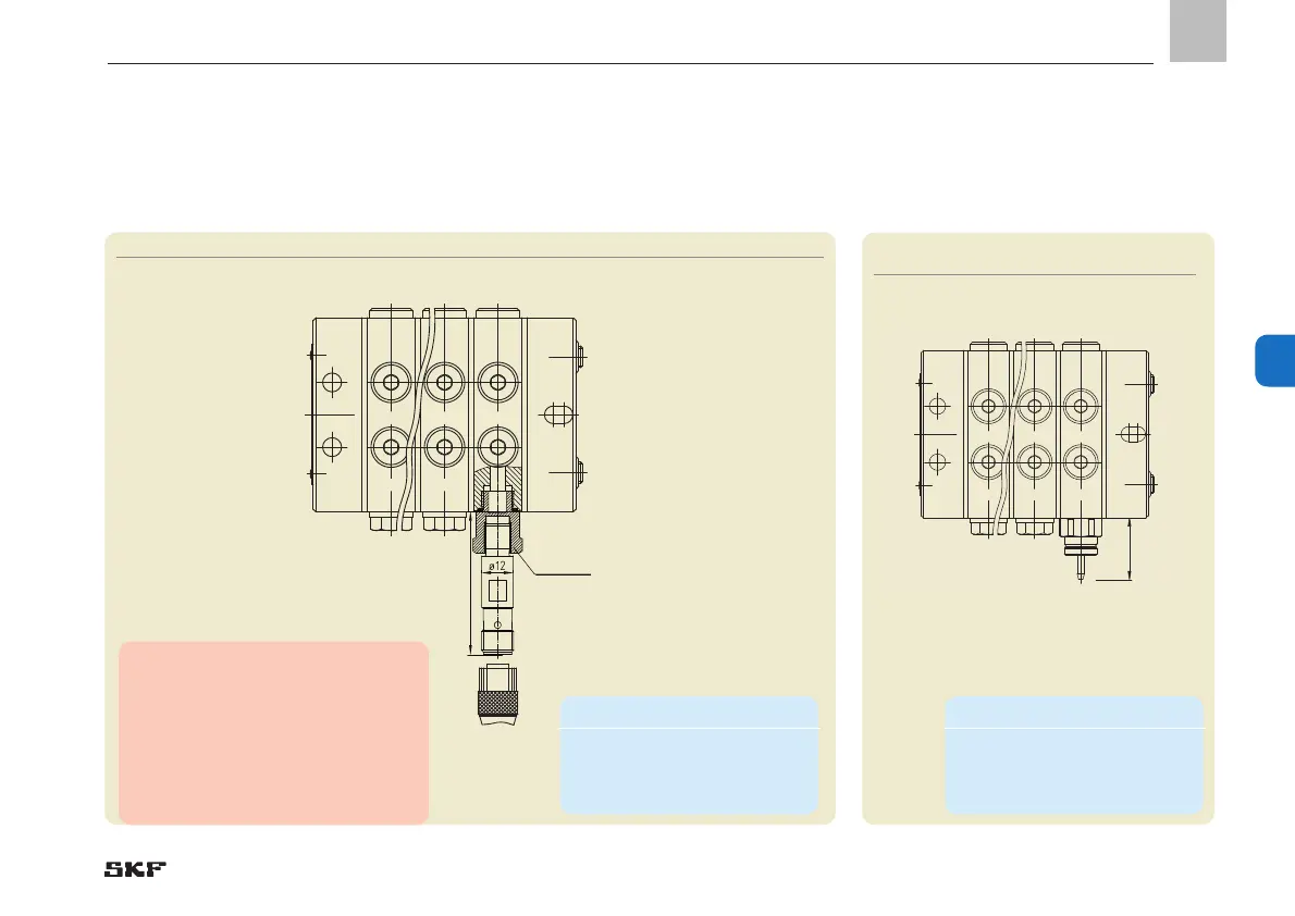
6.3.3 VP with piston detector for oil or grease
Monitoring types P2 / P3 (electric monitoring)
Fig. 13 VP progressive metering device with piston detector
3T
VPM VPM
2T4T
SW 17
44-0159-2509
53,8
6.3.4 VP progressive metering device
with cycle switch
for oil or grease, monitoring type ZY
Fig. 14 VP progressive met-
ring device with cycle indicator
26
VPM
2T
VPMVPM
3T4T
Note!
For piston detector dimensions, see
Technical Data, Chapter 4.4.
Additional technical data on the cable
sockets can be found in brochure
"Electrical Plug and Socket
Connectors,”
brochure No. 1-1730-EN.
Minimum mounting dimensions
W = width: 130 mm
H = height 45 mm
L = Length L2+10 mm
Minimum mounting dimensions
W = width: 160 mm
H = height 45 mm
L = Length L2+10 mm
- 51 -
951-230-008-EN
Version 04
EN
 Loading...