6. Assembly
6
6.10 Electrical connection
Connect the power cables in such
a way that no forces are trans-
ferred to the product (stress-free
connection).
See the electrical data for the
inductive NAMUR sensor,
Chapter 4, Technical Data
Only attachments and monitoring equip-
ment approved by SKF for the progressive
metering devices may be installed.
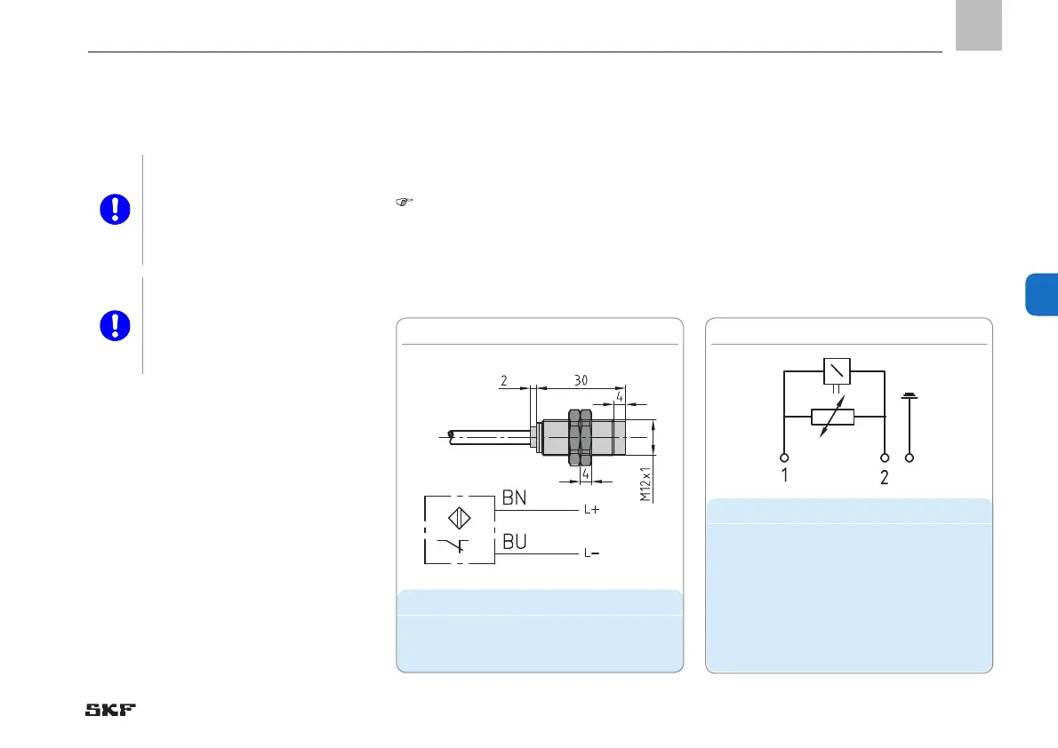
6.10.1 Connecting the inductive
NAMUR sensor (VPK)
-see Figure 43
See electrical data for VPK, page 39
• Connect inductive NAMUR sensor ac-
cording to terminal diagram in Figure 43.
6.10.2 Connecting directional solenoid
valves
-see Figure 44
- See electrical data for directional solenoid
valves, VP page 35; VPK page 40 and VPB
page 43.
• Connect directional solenoid valve ac-
cording to terminal diagram in Figure 44.
Housing
Spare parts
Designation Order number
NAMUR sensor 177-300-075
Spare parts
Designation Order number
For grease
2/2 directional solenoid
valve
161-110-031+924
3/2 directional solenoid
valve
161-140-050+924
For oil
VPG VPG-VEN+924
VPM VPM-VEN+924
Fig. 43 Connecting inductive NAMUR sensor Fig. 44 Connecting directional solenoid valves
- 85 -
951-230-008-EN
Version 04
EN
 Loading...