3
2 71
4
5
1
7
5 6
6
3
4
2
8
8
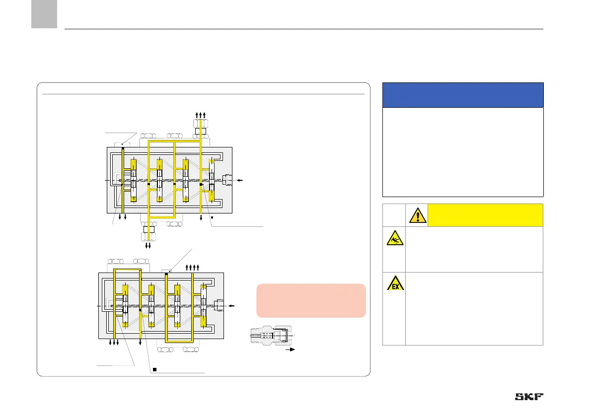
Plug screw 466-431-001
Plug
917-006-101 removed
Plug 917-006-101 (hexagon socket WAF 3)
Plug screw 466-431-001
Plug 917-006-101 (hexagon socket WAF 3)Plug
917-006-101 removed
Note!
Use only a fitting with check valve (VP-
KM-RV-S4) on the progressive metering
device outlet.
6.6 Lubrication line connection
IMPORTANT NOTE
Outlets of a progressive metering device
that are not needed must not be closed
because this will cause the progressive
metering device to block.
Consolidate unneeded outlets with a
neighboring outlet or connect them to the
pump via the return line.
CAUTION
Exercise caution when handling
lubricants; immediately bind and
remove any leaked lubricants.
The customer must take appropri-
ate precautions to ensure that no
contamination enters the lubricant
and thus the progressive metering
device.
- 80 -
951-230-008-EN
Version 04
EN
 Loading...