6. Assembly
6
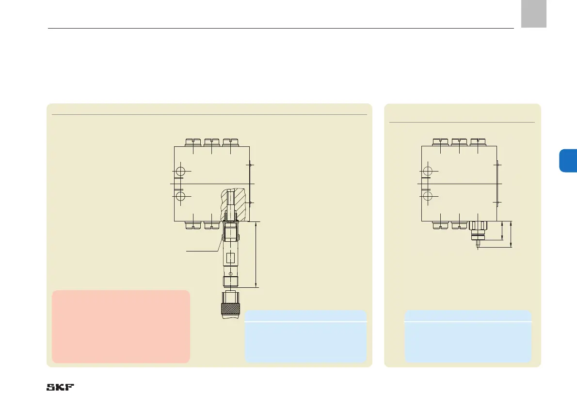
Monitoring types P2 and P3 (electric monitoring)
Fig. 33 VPB progressive metering device with piston detector
6.5.2 VPB with piston detector for oil or grease 6.5.3 VPB progressive metering device
with cycle switch
for oil or grease, monitoring type ZY
Fig. 34 VPB progressive mete-
ring device with cycle indicator
21
4
5
3
SW 12
44-0159-2507
53,6
15
21
2
1
6
4
5
3
Note!
For piston detector dimensions, see
Technical Data, Chapter 4.4.
Additional technical data on the cable
sockets can be found in brochure
"Electrical Plug and Socket Connec-
tors,” brochure No. 1-1730-EN.
Minimum mounting dimensions
W = width: 140 mm
H = height 35 mm
L = Length L+10 mm
Minimum mounting dimensions
W = width: 110 mm
H = height 35 mm
L = Length L+10 mm
- 75 -
951-230-008-EN
Version 04
EN
 Loading...