VPMVPM
2T
VPM
4T
p
R
K
3
p
1
D
2
D
1
2
p
F
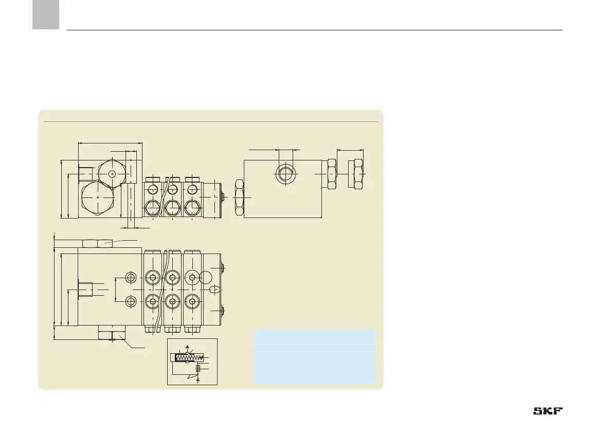
p1 Pressure upstream of nozzle D1
p2 Pressure downstream of nozzle D1
D1 Nonadjustable restrictor (plug-in nozzle)
D2 Adjustable restrictor
RK Control piston
F Spring force
p3 Pressure downstream of D2 (outlet pressure)
6.3.5 VP progressive metering device with flow limiter
for oil, attachment 07
Functioning of the flow limiter
The flow limiter installed on the VP progres-
sive metering device has two restrictors
installed in series (D
1
, D
2
). Restrictor D
1
is
an interchangeable plug-in nozzle which,
as a nonadjustable restrictor, determines
the rated volumetric flow. The nonadjust-
able restrictor D
1
is available in different
nozzle sizes (see table). Restrictor D
2
, on the
other hand, is adjustable and has a variable
nozzle size depending on the position of
control piston RK. Displacement of the con-
trol piston (RK) against the spring force (F)
automatically changes the flow resistance
of restrictor D
2
in such a way that the dif-
ferential pressure at nonadjustable restrictor
D
1
remains constant, as does the volumetric
flow as a result.
Fig. 15 VP progressive metering device with flow limiter
Minimum mounting dimensions
W = width: 160 mm
H = height 65 mm
L = Length L2+80 mm
- 52 -
951-230-008-EN
Version 04
EN
 Loading...