6. Assembly
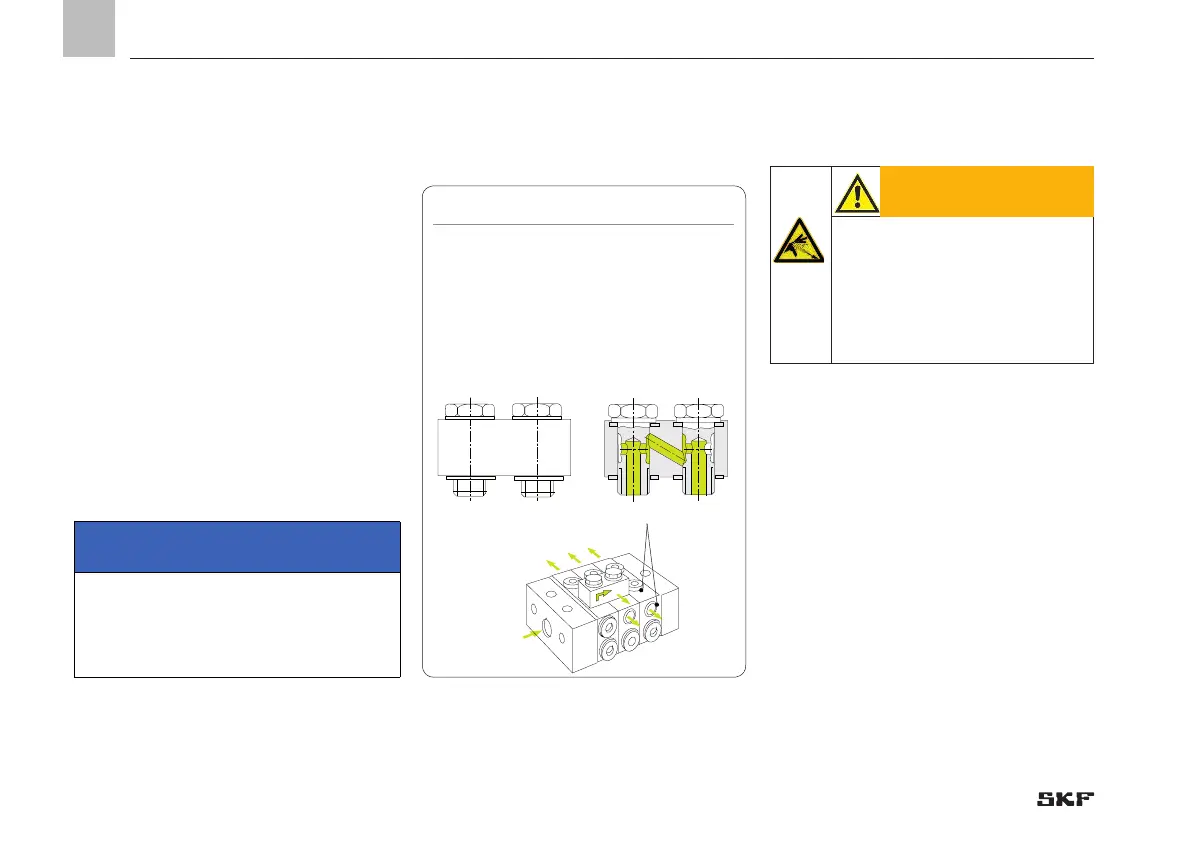
6.3.11 Connecting outlets on the VPM
In the VPM series, the progressive metering
device sections have two outlets on each
side, one on the side and one on the top,
however only one may be used. The second
outlet must always be kept closed.
Outlets can only be subsequently consoli-
dated by using a VP-C crossporting bar that
is screwed in the upper alternative outlets.
Any odd number of outlets can be achieved
with the help of single sections without ad-
ditional crossporting bars.
Fig. 20 Attachment of a
VPM crossporting bar
Alternative outlets; use only one
IMPORTANT NOTE
Use only one outlet, either outlet top or
side.
Crossporting is possible in both directions.
Crossporting bars, design complete
with banjo bolt and sealing rings.
Order No. for VP-C
6.3.12 Modification of a piston detector
• Depressurize the lubrication system and
progressive metering device.
• If possible, place a drip pan for the dis-
charging lubricant below the progressive
metering device.
• Loosen electrical power lead.
WARNING
System pressure
Pressure must not be applied to
the progressive metering device
section during the retrofitting de-
scribed below. Depressurize the
progressive metering device.
Retrofitting of the piston detector from a
right-sided attachment to left-sided attach-
ment is described below. The steps are iden-
tical for reverse retrofitting from left to right.
- 58 -
951-230-008-EN
Version 04
EN
 Loading...