Section 06 ELECTRICAL
Subsection 03 (TESTING PROCEDURE)
MMR2000_129_06_03A.FM 06-03-1
TESTING PROCEDURE 0
IGNITION SYSTEM TESTING
SEQUENCE
In the case of ignition problems, check the follow-
ing in the prescribed order until the problem can
be solved.
1. Sparking/spark plug condition
2. Electrical connectors
3. Ignition switches, tether cord cap switch and
emergency switch
4. Ignition coil resistance
LIGHTING SYSTEM TESTING
SEQUENCE
1. Electrical connectors
2. Lamp coil resistance
Analysis of Readings
Resistance Readings
Place multimeter selector switch to Ω in order to
measure resistance. Readings must be within the
indicated range. Otherwise, the part is considered
to be defective and must be replaced.
CAUTION: When taking measurements, it is
useless to try to start the vehicle since readings
would then be distorted.
Intermittent Ignition Problems
It is difficult to make a diagnostic in the case of
intermittent ignition problems. Thus, problems oc-
curring only when the engine operating tempera-
ture is normal must be checked in similar condi-
tions.
In most cases when problems are caused by tem-
perature or vibrations, these can only be solved by
replacing parts. Most problems cannot be detect-
ed when the engine is stopped.
Multiple Problems
As a matter of fact, more than one component can
be defective. As a result, if the problem remains
although a part was replaced, start over the whole
verification from the beginning in order to identify
the other defective component.
1. SPARKING
During this operation, it is important to use the
snowmobile spark plug and not a new one. Bring
the plug in contact with the engine. If no spark is
produced, replace the spark plug with a new one
and do the test again.
2. ELECTRICAL CONNECTOR
TESTING
Make sure that none of the connectors are discon-
nected.
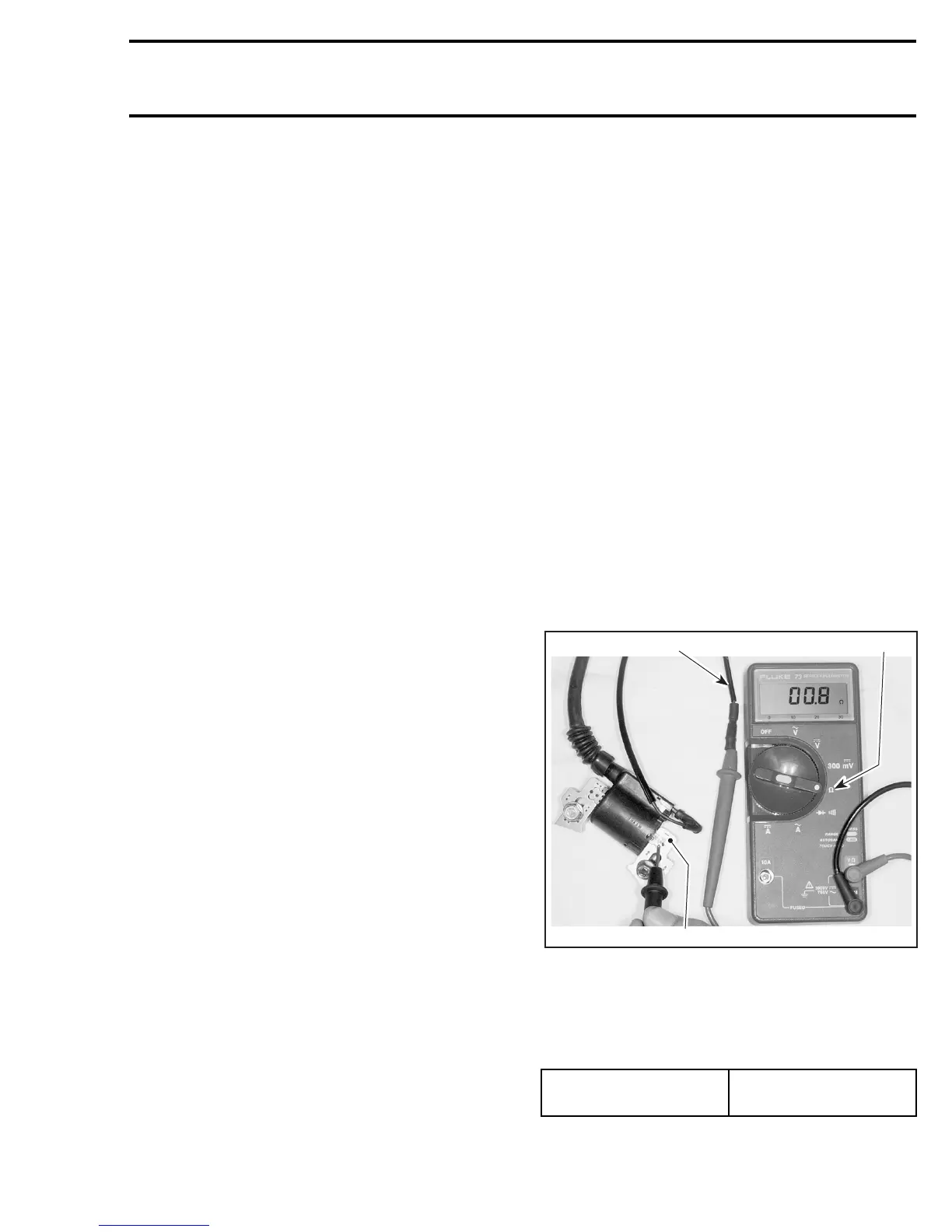
3. IGNITION COIL TESTING
Primary Side
Bring multimeter selector switch to Ω position.
Connect first multimeter probe to ignition coil pri-
mary black wire then second probe to ignition coil
iron core, as shown in the next photo.
PRIMARY SIDE TESTING
1. Multimeter to
Ω
position
2. Ignition coil primary black wire
3. Ignition coil iron core
The measured resistance should be according to
the following table. If not, replace ignition coil.
PRIMARY SIDE
RESISTANCE VALUE
0.8 - 1.0 Ω
A31E0FA
1
2
3
 Loading...