Section 04 ENGINE
Subsection 05 (COMPRESSION TEST AND ENGINE DIMENSION MEASUREMENT)
MMR2000_120_04_05A.FM 04-05-3
GUIDE-TO-STEM CLEARANCE
Subtract each valve stem outside diameter from
the corresponding valve guide inside diameter to
obtain the stem-to-guide clearance.
If the stem-to-guide clearance exceeds the ser-
vice limit value, replace valve or cylinder head as
needed.
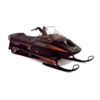
CYLINDER HEAD SURFACE
Clean cylinder head surface.
Check cylinder head flatness with a straight edge
and a feeler gauge, as shown in the next photo.
1. Straight edge
2. Feeler gauge
If cylinder head flatness is over service limit value,
replace cylinder head.
Cylinder Head Inspection
Remove carbon deposits from combustion cham-
ber.
Check the spark plug hole and valve areas for
cracks.
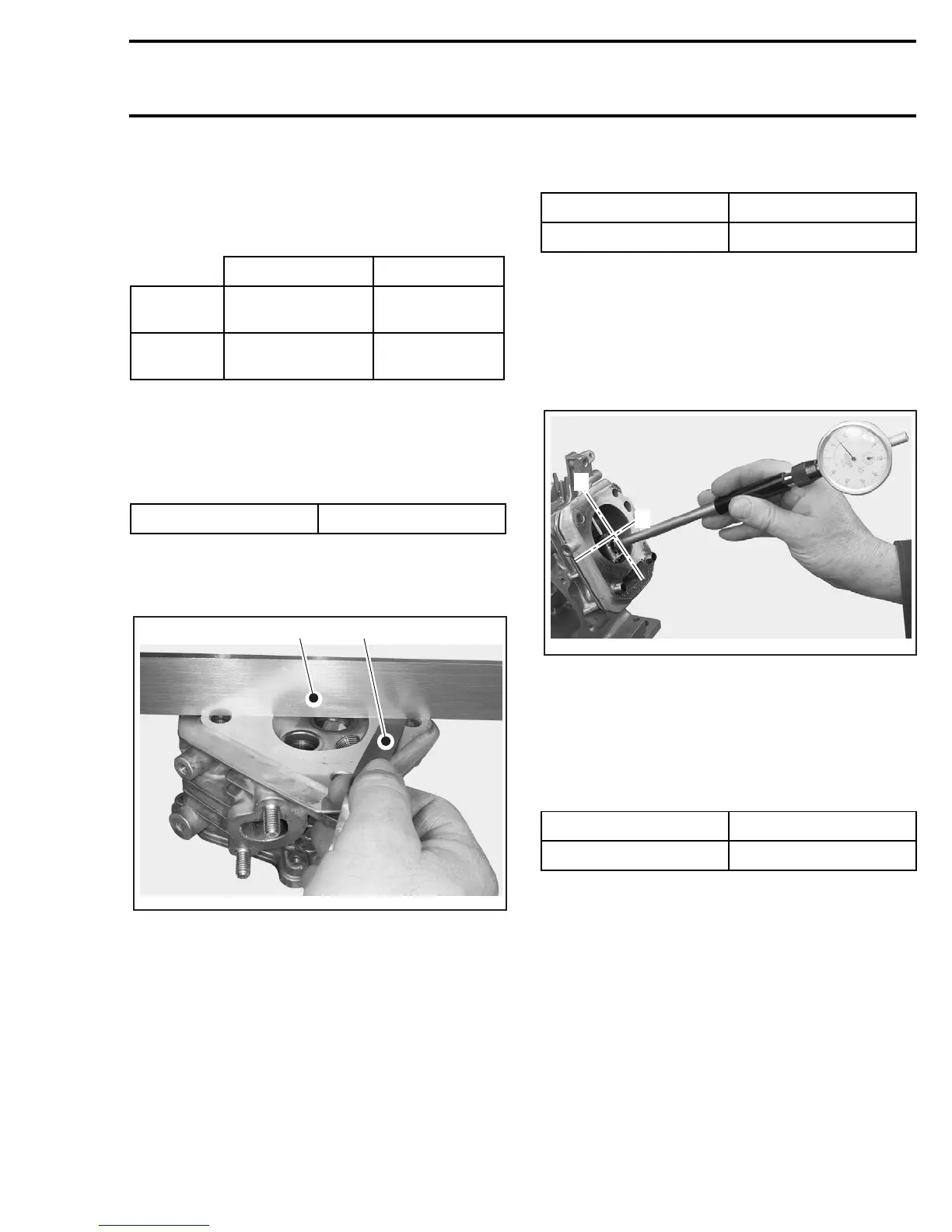
CYLINDER INSIDE DIAMETER
Compare cylinder inside diameter 16 mm (5/8 in)
from top of cylinder, halfway and 12.7 mm (1/2 in)
from bottom of cylinder.
Measure cylinder inside diameter in both X (per-
pendicular to crankshaft) and Y (parallel to crank-
shaft) axis. Take the maximum reading to deter-
mine cylinder wear.
X: Axis (perpendicular to crankshaft axis)
Y: Axis (parallel to crankshaft axis)
If the difference exceeds the specified dimension
the cylinder should be rebored and honed or
should be replaced.
USED PISTON MEASUREMENT
Using a micrometer, measure piston at 10 mm
(25/64 in) perpendicularly (90°) to piston pin.
STANDARD SERVICE LIMIT
INTAKE
0.020 - 0.044 mm
(0.0008 - 0.0017 in)
0.10 mm
(0.004 in)
EXHAUST
0.006 - 0.087 mm
(0.0024 - 0.0034 in)
0.12 mm
(0.005 in)
SERVICE LIMIT 0.10 mm (0.004 in)
A31C1OA
1
2
STANDARD SERVICE LIMIT
60.0 mm (2.36 in) 60.165 mm (2.3687 in)
STANDARD SERVICE LIMIT
59.985 mm (2.3616 in) 59.845 mm (2.3561 in)
A31C1PA
X
Y