Section 07 REAR SUSPENSION
Subsection 03 (DRIVE AXLE)
07-03-2 MMR2000_131_07_03A.FM
REMOVAL
Remove chain guard.
Remove drive chain then remove driven sprocket.
NOTE: To ease driven sprocket and drive axle re-
moval, it may be useful to remove left side foot-
rest.
Remove rear suspension. Refer to REAR SUS-
PENSION 07-02 of this manual.
Sprocket
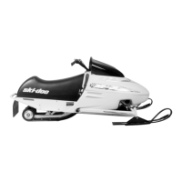
From inside tunnel, remove spring pin no. 1 from
right side sprocket using a hammer and a punch,
as shown.
REMOVE SPRING PIN
Using a prybar and a piece of wood (to protect tun-
nel), slide right side sprocket no. 2 (38 mm (1-1/2 in)).
See the next photo.
NOTE: Apply BOMBARDIER LUBE (P/N 293 600
016 — 12 x 14 oz) on drive axle to ease sliding
sprocket.
CAUTION: When using prybar, ensure not to
apply too much pressure on tunnel wall in or-
der to avoid damaging tunnel.
SLIDE RIGHT SIDE SPROCKET INSIDE
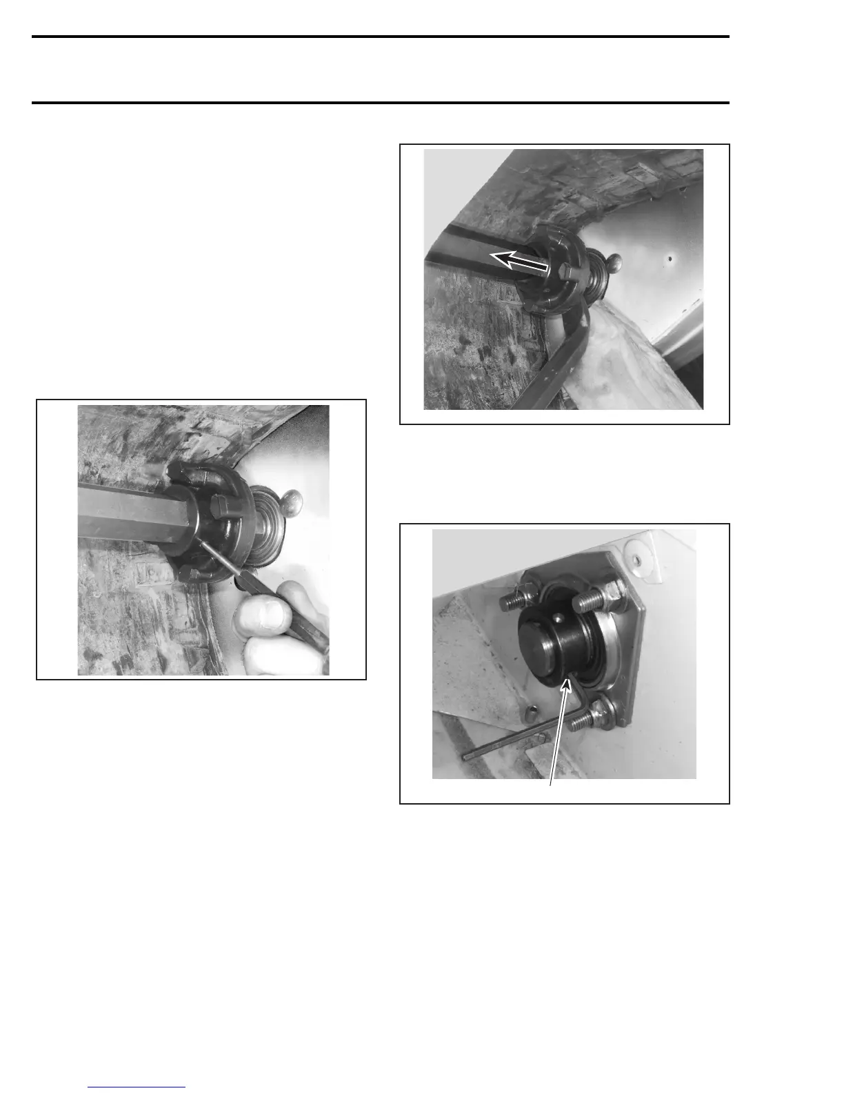
Bearing Holder
Using Allen key loosen set screw no. 3 from bear-
ing lock sleeve no. 4, as shown in the next photo.
RIGHT SIDE SHOWN
1. Loosen set screw
Using a hammer and a punch, turn CCW to unlock
bearing lock sleeve as shown.
A31D0OA
A31D0PA
A31D0QA
1