Section 04 ENGINE
Subsection 04 (DISASSEMBLY/ASSEMBLY)
04-04-6 MMR2000_119_04_04A.FM
NOTE: Engine must be removed from chassis to
perform the following procedures.
CLEANING
Discard all oil seals and gaskets.
Clean all metal components in a non-ferrous metal
cleaner.
DISASSEMBLY
General
To remove clutch, refer to CLUTCH 05-02.
To remove magneto, refer to TRANSISTORIZED
MAGNETO IGNITION 04-06.
Crankcase
Drain all oil from engine base.
Remove crankcase cover no. 1 on PTO side.
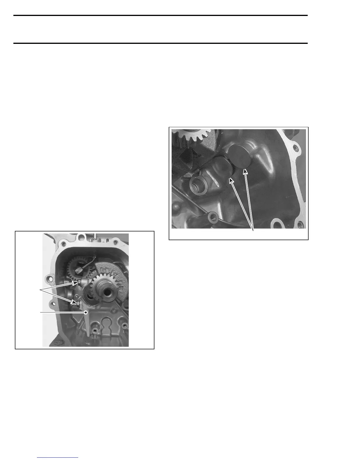
From inside crankcase, loosen both connecting
rod screws no. 2 then remove connecting rod cap
no. 3.
1. Connecting rod screws
2. Connecting rod cap
Push on connecting rod no. 4 and pull out piston
no. 5.
Remove both piston pin circlips no. 6 and push out
piston pin no. 7.
Detach piston from connecting rod.
Remove crankshaft no. 8 and camshaft ass‘y no. 9.
Mark both valve lifters and remove them. This will
ensure that lifters will not be inverse at reassembly.
MARK BOTH VALVE LIFTERS FOR REASSEMBLY
1. Valve lifters
Seals and Bearings
To remove seals nos. 10 and 11, push from inside
crankcase towards the outside.
To remove bear ings nos. 12 and 13, use a press
with all 3 following tools:
– driver (P/N 529 035 521)
– attachment (P/N 529 035 522)
– pilot (P/N 529 035 523)
A31C2DA
1
2
A31C2EA
1
 Loading...