Section 04 ENGINE
Subsection 05 (COMPRESSION TEST AND ENGINE DIMENSION MEASUREMENT)
MMR2000_120_04_05A.FM 04-05-7
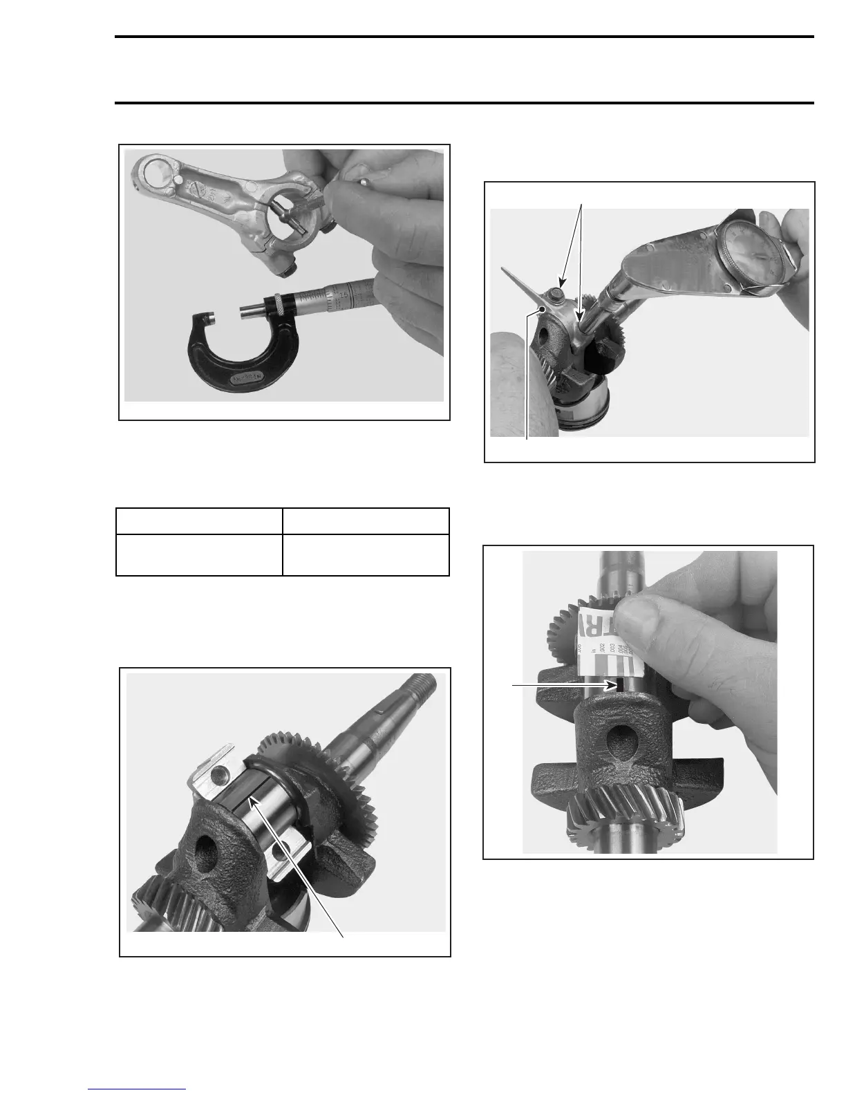
MEASURE CONNECTING ROD BIG END
CONNECTING ROD BIG END OIL
CLEARANCE
Clean all oil from crankpin and connecting rod big
end surfaces.
Position a piece of plastigauge on the crankpin, as
shown on the next photo.
1. Plastigauge properly positioned
Reinstall connecting rod cap and torque screws to
12 N•m (109 lbf•in). See next photo.
NOTE: Do not rotate crankshaft while plastigauge
is in place.
1. Connecting rod cap in place
2. Torque both screws
Remove connecting rod cap and measure the
plastigauge, as shown in the next photo.
1. Plastigauge
If clearance exceeds the service limit, replace con-
necting rod and recheck clearance.
NOTE: Replacement connecting rods are avail-
able with standard and 0.25 mm (0.010 in) under-
size bearing surfaces.
STANDARD SERVICE LIMIT
0.040 - 0.063 mm
(0.0016 - 0.0025 in)
0.12 mm
(0.005 in)
A31C1WA
A31C1XA
1
A31C1YA
2
1
1
A31C1ZA