Section 11 WIRING DIAGRAM
Subsection 01 (WIRING DIAGRAM)
MMR2000_137_11_01A.FM 11-01-1
WIRING DIAGRAM 0
WIRING DIAGRAM LEGEND
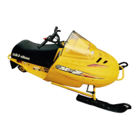
1. Wire colors
2. Housing area
3. Housing number per area
4. Wire connector location in housing
WIRE COLORS AND CIRCUIT
The first color of a wire is the main color, second
color is the stripe.
Example: YL/BK is a YELLOW wire with a BLACK
stripe.
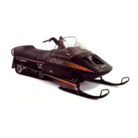
CONNECTOR HOUSING AREA
WARNING
Ensure all terminals are properly crimped on the
wires and all connector housings are properly
fastened.
COLOR CODE
BK – BLACK
BL – BLUE
BR – BROWN
GN – GREEN
GY – GREY
OR – ORANGE
PK – PINK
RD – RED
VI – VIOLET
WH – WHITE
YL – YELLOW
A00I04A
XX/XX
1-02D
1
2 3 4
A00I04B
1-02D
XX/XX
XX/XX
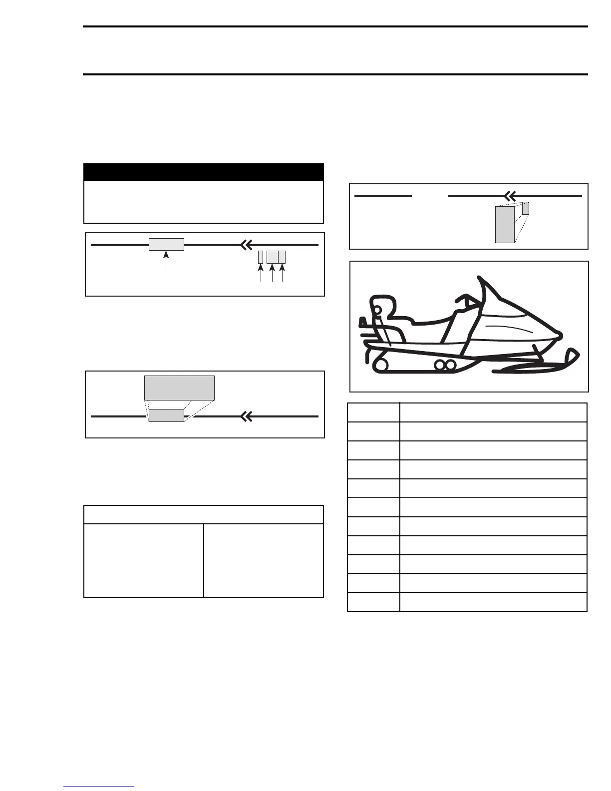
AREA LOCATION
1 Front of engine compartment
2Magneto
3 Carburetors
4 Near intake silencer
5 Near driven pulley
6 Under console
7 Under hood
8 Near fuel tank
9 Rear of seat
10 Under engine
XX/XX
A00I04C
1 -02D1
1
A06H33B
1
7
6
9
8
4
5
3
2
10
 Loading...