173
SJ1044 TH, SJ1044 THS, SJ1056 TH, SJ1056 THS, SJ1256 THS
230790ABA
Non-Routine Maintenance Section 5 – Procedures
3. Tighten the lock nut on the valve RV2 and re-
check the reading to ensure that the correct
pressure is maintained.
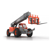
Service Brake Pressure
▪
Service Brake Pressure Check:
1. Release residual pressure by moving the joystick
several times in each direction.
2. Remove plug and install a 1,000 psi gauge into
the PS2 port on the main control valve.
PS2
Figure 106 Service Brake Pressure
3. With engine running at low idle, depress
brake pedal fully. Pressure should increase
proportionally to 900 psi MAX.
4. If maximum pressure is less than 900 psi, brake
valve must be replaced.
5. note
6. The pressure setting value is the nominal
maximum value.
IMPORTANT
There is no adjustment. Replace the brake valve at
the service brake pedal.
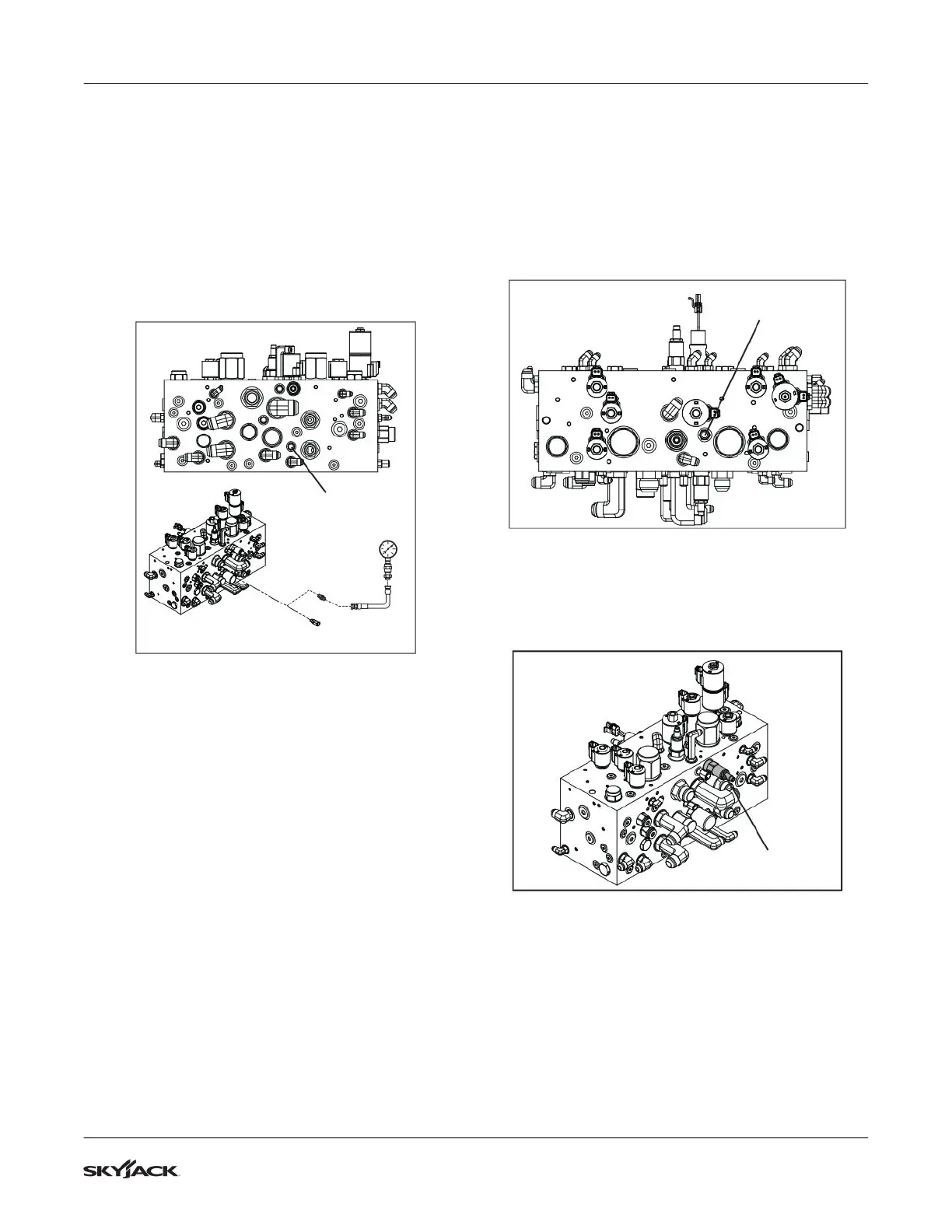
Pilot Pressure
▪
Pilot Pressure Check:
1. Release residual pressure by moving the joystick
several times in each direction.
2. Install a 1,000 psi gauge into the tee fitting at port
GP2 of the hydraulic function manifold.
3. With engine running at low idle and NO hydraulic
function engaged, pressure should be 400 psi.
GP2
Figure 107 Pilot Pressure Check
▪
Pilot Pressure Adjustment:
1. Loosen the lock nut on the pressure reducing
valve at port PR1 on the Main Control Valve.
PR1
Figure 108 Pilot Pressure Adjustment
2. With engine running at low idle, turn the
adjustment screw clockwise (CW) to increase the
pressure reading and counter-clockwise (CCW) to
reduce the pressure reading until a reading of 400
psi is achieved.
3. Tighten the lock nut on valve PR1 and re-check
the reading to ensure that the correct pressure is
maintained.
 Loading...