175
SJ1044 TH, SJ1044 THS, SJ1056 TH, SJ1056 THS, SJ1256 THS
230790ABA
Non-Routine Maintenance Section 5 – Procedures
5.6-5 Hydraulic Pump Testing Procedure
If the hydraulic pump is suspected to be bad, the
following test will quickly determine if the hydraulic
pump requires replacement.
1. Release residual pressure by moving the joystick
several times in each direction
2. Remove LS hose on the main manifold and cap
the fitting on the manifold.
3. Install a 5,000 psi gauge with a tee fitting on the
GP1 port of the main manifold.
4. Install the LS hose to the tee fitting on the GP1.
LS Port to
Port X on
Hyd. Pump
To Port X on
Hyd. Pump
LS Port
GP1
Connect
Pressure
Gauge
Figure 111 Pump Pressure Adjustment
5. Start the engine and check the gauge. Maximum
system pressure should immediately be present
(3,250 psi).
6. If the pressure reading is different than the
required pressure, use the pressure adjustment
screw on the pump to adjust the pressure to the
proper level.
7. If the required pressure cannot be set, the pump
must be replaced.
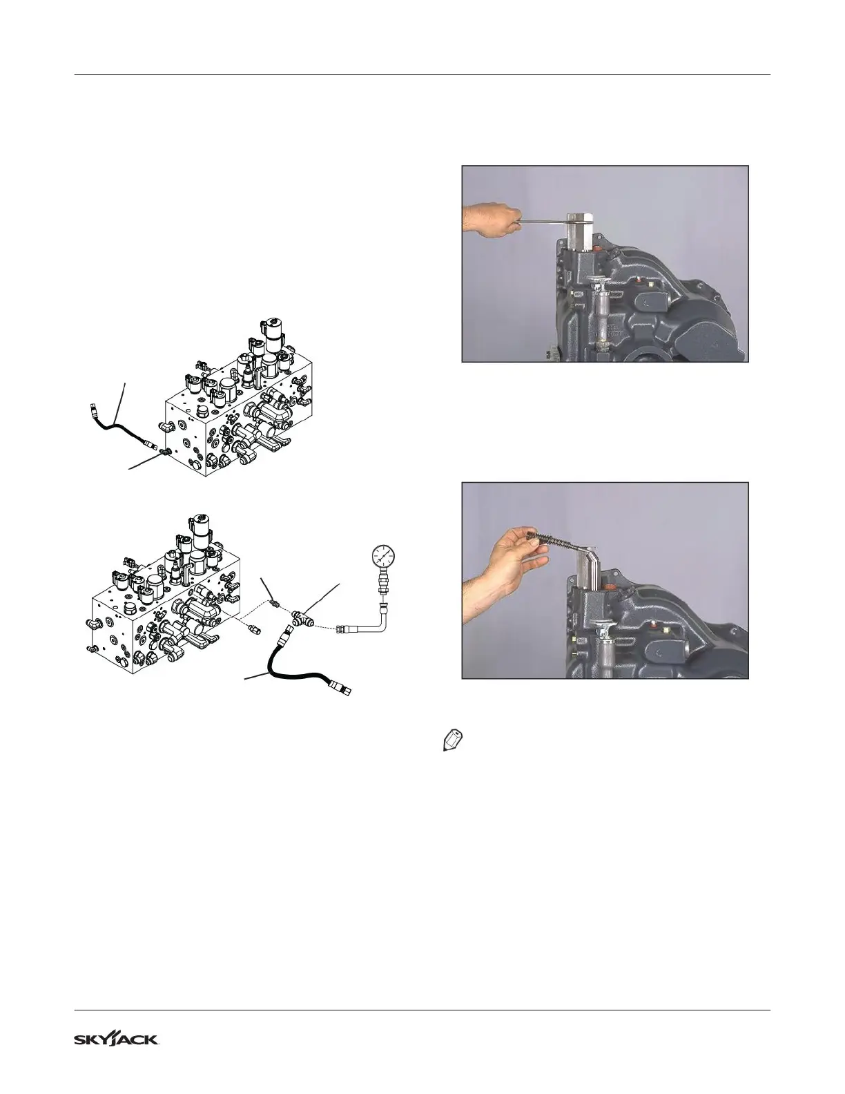
5.6-6 T12000 Modulation
1. Remove modulator valve housing as shown in
figure below.
Figure 112 Remove Modulator Valve Housing
2. Remove inner, middle and outer springs, valve
stop pin and accumulator spool and regulator
spool and sleeve assembly as shown in figure
below.
Figure 113 Remove Modulator Valve Components
NOTE
Some units will have two cross pins the same
length. Some units will have two pins of different
lengths. The longest pin goes in the bottom hole.