199
SJ1044 TH, SJ1044 THS, SJ1056 TH, SJ1056 THS, SJ1256 THS
230790ABA
Electronic Tilt Switch Setup Procedure Section 5 – Procedures
Red LED
Green LED
2. Red and greed LEDs
will flash alternatly.
IMPORTANT
Step 3 must be completed within a 5 second
period or the switch will automatically exit program
mode and return to normal operation using
previously stored data.
3. Press and release set zero button 3 times.
4. If 5 second period has expired prior
completion, repeat Step “a”, “b” and “c”.
Red LED
Green LED
5. Observe
program delay /
stabilization time. (Only
the red LED will blink for
4 seconds)
Red LED
Green LED
6. Both LEDs will flash
alternately for 1 second.
Results: The switch is
learning the new zero
position.
Red LED
Green LED
7. Both LEDs will turn on
solid for 1 -2 seconds.
Results: The new zero
position has been
learned.
8. Turn ignition switch to “ ” off position and
remove key from ignition switch.
9. Remove chocks or wheel blocks.
10. Proceed to Test and Verify Tilt Circuit/Boom
Interlock.
5.7-3 Test and Verify Tilt Circuit
Red LED
Green LED
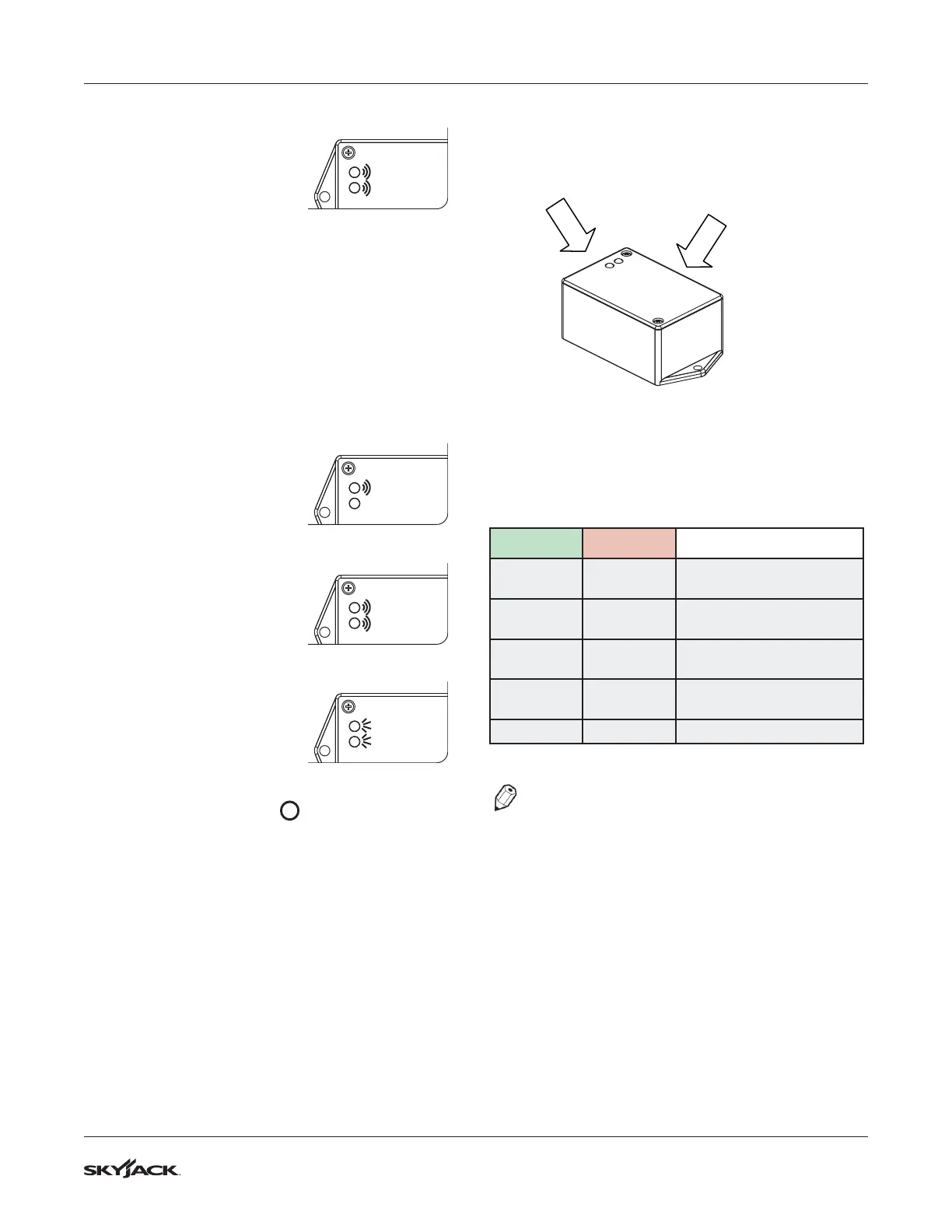
Light Indicators
Set up button is located on this
face next to harness
Operations of Tilt Switch
The following describes the LED’s and what they
indicate.
Green LED Red LED
Meaning
ON OFF
Tilt is within the specified
angle limits.
ON BLINKING
Transitioning from
un-tilted to tilted state.
OFF ON
Tilt is outside of the
specified angle limits.
BLINKING ON
Transitioning from tilted to
un-tilted state.
ON ON
Output fault detected.
NOTE
Observe program delay / stabilization time.
Tilt Circuit Test
Refer to Section 2 - Function Tests of the operating
manual to Test Frame Leveling and Boom Interlock.