6 Electrical Connection
SMA Solar Technology AG
Operating manual EVC22-3AC-20-BE-en-10 49
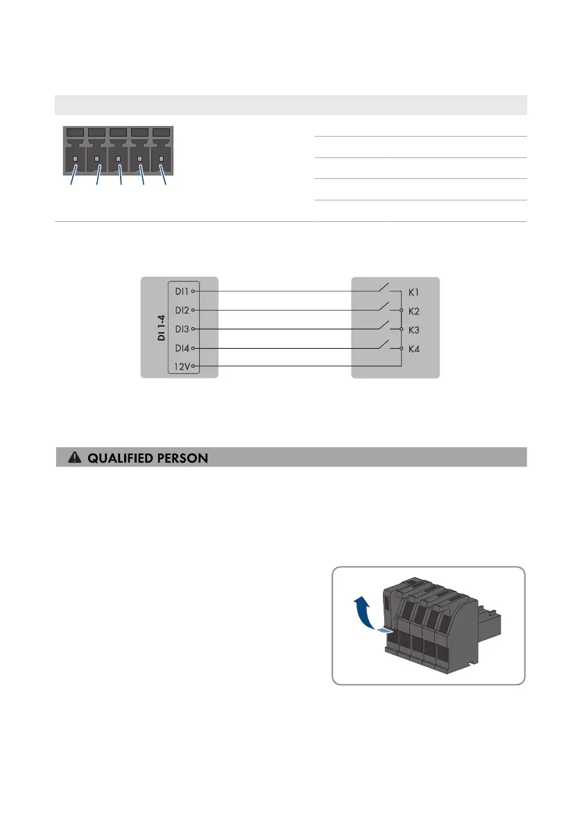
6.6.2 Pin assignment DI 1-4
Digital input D1-4 Pin Assignment
1 Digital input1
2 Digital input2
3 Digital input3
4 Digital input4
5 Voltage supply output
6.6.3 Circuitry overview DI 1-4
SMA eCharger as System Manager Ripple control receiver
Figure 13: Connect a ripple control receiver to digital input DI 1-4 of the SMA eCharger that is to be configured
as System Manager
6.6.4 Connecting the ripple control receiver to DI 1-4
Procedure:
1. Connect the connection cable to the ripple control receiver or the remote terminal unit (see the
manual from manufacturer).
2. Disconnect the charging station from voltage sources (see Section9, page81).
3. Strip 6mm of the cable insulation at maximum.
4. Release the conductor entries on the supplied 5-pole
plug.