6 Electrical Connection
SMA Solar Technology AG
Operating manualEVC22-3AC-20-BE-en-1050
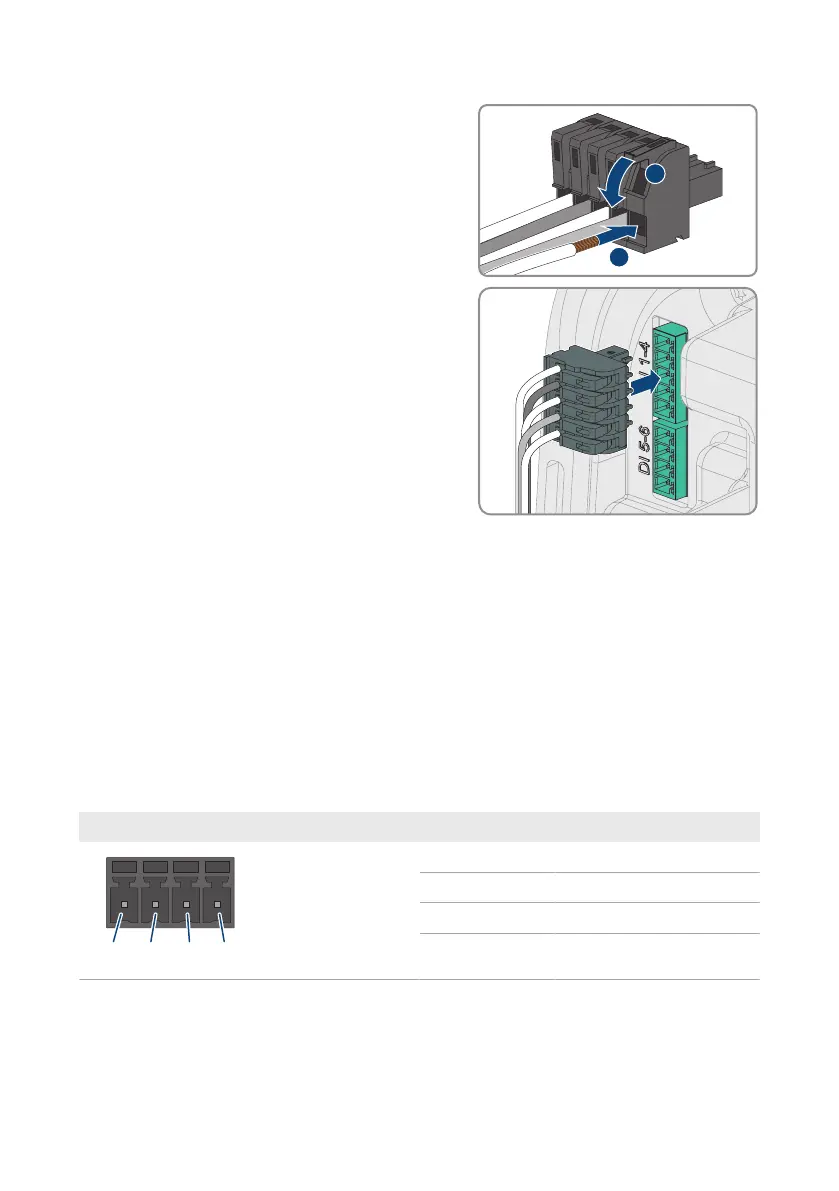
5. Connect the conductors of the connection cable to
the supplied five-pole connector. To do so, plug the
conductors into the conductor entries and close the
conductor entries. Observe the connector
assignment.
6. Plug the five-pole connector into the port DI 1-4 on
the product. Observe the pin assignment.
7. Ensure that the connector is securely in place.
8. Ensure that all conductors are correctly connected.
9. Ensure that the conductors sit securely in the terminal points.
6.7 Connection to digital input DI 5-6
6.7.1 Digital input DI 5-6
You can connect a fast-stop switch at digital input DI5.
You can connect a relay for an external grid and PV system protection device at digital input DI6.
In a system with multiple charging stations, each charging station must be connected to the relay.
6.7.2 Pin assignment DI 5-6
Digital input Pin Assignment
1 Digital input5
2 Voltage supply: (+12 V)
3 Digital input6
4 Voltage supply: (+12 V)