6 Electrical Connection
SMA Solar Technology AG
Operating manual EVC22-3AC-20-BE-en-10 51
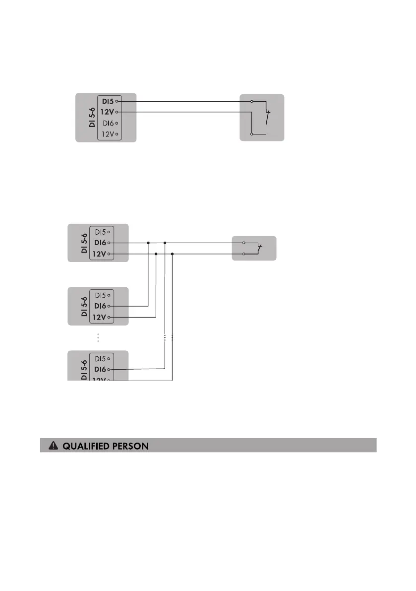
6.7.3 Circuitry overview DI 5
SMA eCharger as System Manager
Fast-stop switch
Figure 14: Connect a switch for the fast stop to digital input DI5 of the charging station that is to be configured
as System Manager
6.7.4 Circuitry overview DI 6
System protection
Relay for the grid and PV
system protection
Figure 15: Connect a relay for the external grid and PV system protection device to digital input DI6 of one or
more charging stations in the system
6.7.5 Connecting Signal Source to Digital Input DI 5-6
Additionally required material (not included in the scope of delivery):
☐ 1 relay for the grid and PV system protection (break contact)
☐ 1 fast-stop switch (break contact)
Requirements:
☐ The signal source must be technically suitable for connection to the digital inputs (see
Section15, page101).