General Information Powering the Diagnostic Tool
4
2.2 Powering the Diagnostic Tool
Your diagnostic tool can receive power from any of the following sources:
• Vehicle Power
• Internal Battery Pack
• AC Power Supply
2.2.1 Vehicle Power
The diagnostic tool is designed to be powered from the vehicle. All OBD-II/EOBD
vehicles have vehicle battery power (B+) available on the data link connector
(DLC). The diagnostic tool is powered through the Data Cable when connected to
the vehicle DLC.
A green LED indicator on the DLC end of the data cable, illuminates when power is
being supplied to the cable. If the LED fails to illuminate, check that the data cable
is properly connected and then check the DLC power circuit. See Data Cable /
Connections on page 11 for additional data cable information.
An optional power cable is required when testing non-OBD-II/EOBD or models that
do not have vehicle battery power (B+) available on the DLC. Contact your sales
representative for availability.
Never connect the optional power cable to the power supply input jack
on the diagnostic tool when the diagnostic tool is communicating with a
vehicle.
2.2.2 Internal Battery Pack
The diagnostic tool can be powered from the internal rechargeable battery pack. A
fully charged battery pack provides sufficient power for about 3 hours of continuous
operation. For battery pack removal and installation instructions see, Removing /
Installing the Battery Pack on page 95.
Battery Pack Charging
Battery charging occurs whenever the data cable is connected to a vehicle DLC.
Battery charging also occurs when the AC power supply is connected to a live AC
power source, and connected to the diagnostic tool. Use the supplied AC power
supply to charge the battery pack.
Insert the end of the AC power supply cable into the diagnostic too power supply
jack, then connect the AC power supply to an approved AC power source.
Only use the supplied AC power supply. Never connect the power supply
to the diagnostic tool when the tool is communicating with a vehicle.
The Battery Status Indicator LED (located next to the power supply jack) indicates
battery status.
2.2.3 AC Power Supply
The diagnostic tool can be powered from a standard AC outlet using the AC power
supply. The AC power supply converts alternating current (AC) to direct current
(DC) to power the diagnostic tool. The connector on the end of the output cable of
the AC power supply connects to the AC power supply jack on top of the diagnostic
tool. Use only the AC power supply provided.
Never connect the AC power supply to the diagnostic tool when the
diagnostic tool is communicating with a vehicle.
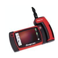
Battery Status LED Description
Green - battery is fully charged, or the diagnostic tool is
being powered by the AC power supply.
Red - battery is charging
Amber - indicates a battery issue. This is usually caused
by excessive battery temperature (above 104°F/40°C),
which disables charging. Allow the diagnostic tool to cool
down before continuing operation.