38 EN
ISOM DIGIWARE - 546780C - SOCOMEC
Description of the terminals
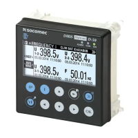
ISOM Digiware D-15h
DIGIWARE DIGIWARE
DIGIWARE
BUS
!
DIGIWARE
BUS
!
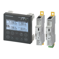
ISOM Digiware D-55 / D-55h / D-75
NC
RS485
LIYCY-CY
MASTER
Supply
24VDC
(20 W max)
Protection 1A gG
DIGIWARE
ETHERNET
ETHERNET
DIGIWARE
BUS
!
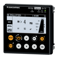
ISOM Digiware L-60
DIGIWARE BUS
14 11
Alarme 1
12 24 21
Alarme 2
22
FE
L2L1KE
θ >
C in
4321
C out
θ >
PTC (120ºC)
Exemple
de câblage
en sortie
Exemple
de câblage
en entrée
Digiware Bus: Digiware bus connection with other
equipment and the Digiware range
14 - 11 - 12: alarm relay output 1
24 - 21 - 22: alarm relay output 2.
It is not permitted for use on a 230V relay or a SELV
signal.
You can use different phases on the2 outputrelays, but
they must be from the same three-phase network.
The relay's dry contacts should be protected with a 2A gG
fuse => use up to 2A with resistive load.
And T3AH250V => use up to 3A with resistive load.
EARTH FE: connection to the earth
Upper terminal Lower terminal
KE - L1 - L2: network voltage Un + earth of booster
θ >: link to la temperature probe (PTC)
C out: shared output link
(Output: 12-24VDC Min 600Ω 40 mA max Input: Max
100Ω)
C in: shared input link
(Max 100Ω)
1 - 2 - 3 - 4: input or output connection (as per
conguration)
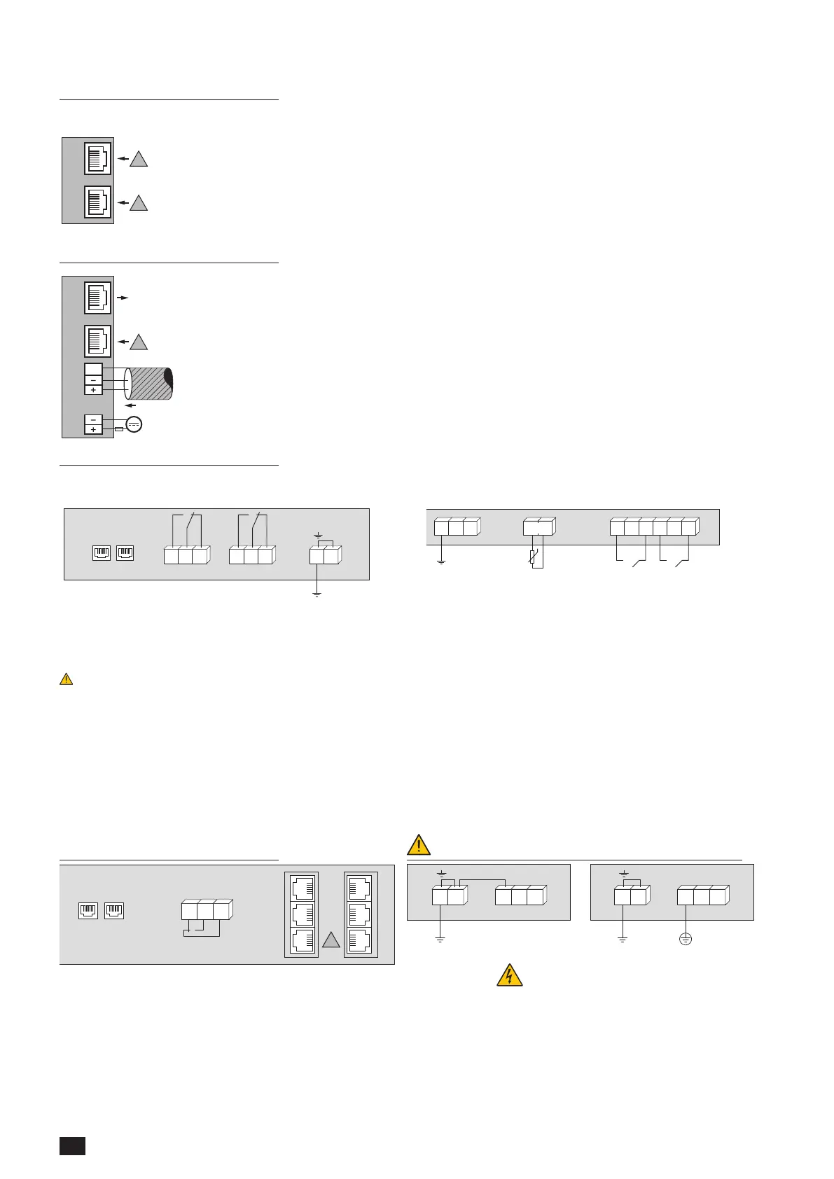
ISOM Digiware F-60 L-60 / L-60h connection
DIGIWARE BUS
RJ45
1214
OUTPUT
24V (1A MAX)
11
I 04
I 05
I 06
I 01
I 02
I 03
!
Digiware bus: Digiware bus connection with other
Digiware devices
11 - 12 - 14: alarm relay output (fuse 1A gG)
I01 - I02 - I03 - I04 - I05 - I06: ISOM T-15 connection
(to core balance transformers) or current sensors TE/TR/
TF
FE
L2L1KE
FE
L2L1KE
Not allowed Authorised