Do you have a question about the socomec ISOM Digiware and is the answer not in the manual?
Safety warnings regarding electrical hazards, burns, and explosion risks.
Precautions to prevent damage to the ISOM Digiware unit during operation.
Outlines responsibilities for installation and use of the unit.
Points to check before starting installation and operation.
General overview of the ISOM Digiware system and its capabilities.
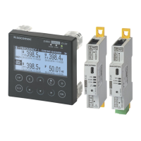
Overview of the different models and product variations available.
Explains the operational principle of the ISOM Digiware system.
Details the various functions and features offered by the ISOM Digiware system.
Lists the electrical parameters and readings supported by the devices.
Provides physical dimensions of ISOM Digiware L-60 and F-60 units.
Introduces the different types of current sensors compatible with ISOM Digiware.
Details the range and specifications of core balance transformers.
Describes the ISOM T-15 adapter for core balance transformers.
Information on TE solid-core current sensors, their range and dimensions.
Information on TR split-core current sensors, their range and dimensions.
Information on TF flexible current sensors, their range and dimensions.
Details the 5A sensor adapter, its range and dimensions.
Safety recommendations and general advice before installation.
Guides on installing ISOM Digiware units on DIN rail or board.
Step-by-step guide for DIN rail mounting of specific ISOM Digiware units.
Instructions for board-mounting ISOM Digiware L-60 and F-60.
Procedures for installing TE solid-core sensors and their accessories.
Lists available mounting accessories for TE sensors.
Shows how to mount TE sensors on a DIN rail.
Details the process for plate mounting TE sensors.
Instructions for installing TE sensors on cables using clamping collars.
Guides for mounting TE sensors on busbars.
Explains TE sensor assembly and sealing accessories.
Instructions for installing TR split-core sensors.
Detailed steps for cable mounting TR split-core sensors.
Mounting procedures for stranded TE sensors on cables or busbars.
Guide for installing the 5A adapter for sensors.
Wiring diagrams and terminal descriptions for connecting ISOM Digiware units.
Explains the connection concept and details for current sensors.
General overview of connecting current sensors to the system.
Specific RJ12 connection details for various current sensor types.
Guidance on connecting the system to different network types.
Table showing load configurations based on network types.
Examples of network and circuit connection combinations.
Explains connection for coupled networks, with and without fault-locating.
Explains the principle of the Digiware bus system and its components.
Lists available Digiware bus connection cables by length and reference.
Details the Digiware bus terminal resistor.
Guidelines for selecting the appropriate power supply for the system.
Table showing power consumption of system components.
Rules for calculating maximum products on the Digiware bus based on power.
Information on using the Digiware bus repeater for extended networks.
Explains the status LEDs and buttons on the ISOM Digiware devices.
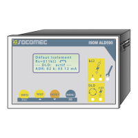
Details the LEDs and buttons for the ISOM Digiware L-60 unit.
Details the LEDs and buttons for the ISOM Digiware F-60 unit.
Details the LEDs for the ISOM T-15 adapter.
Describes the autotest functions of the ISOM Digiware system.
Explains the auto-addressing feature for ISOM and DIRIS Digiware devices.
Overview of communication protocols used by ISOM Digiware.
Rules for connecting ISOM Digiware via RS485 and the Digiware bus.
Specific rules for connecting to the D-55 or D-75 display via RS485.
Reference to communication tables on the Socomec website.
Guide to configuring ISOM Digiware using the Easy Config software.
Describes connection modes for using Easy Config via USB or display.
Step-by-step guide on using the Easy Config software for configuration.
Details on configuring ISOM L-60 and F-60 devices with Easy Config.
How to configure network parameters using Easy Config.
Settings for insulation monitoring configuration using Easy Config.
How to configure I/O settings for ISOM Digiware L-60.
Configuration of loads for the ISOM F-60 module.
Screen for defining calculation methods and integration times.
Configuration for synchronizing time across connected devices.
How to configure the system using the ISOM Digiware D remote display.
Describes connection modes for remote display configuration.
How alarms are generated based on events and thresholds.
Configuration of alarms for insulation and measurement parameters.
Setting up alarms based on digital input status changes.
Creating combined alarms using boolean logic.
Information on system alarms triggered by installation errors.
Methods for identifying and managing alarms.
How the ALARM LED indicates alarm status.
Activating outputs when an alarm is detected.
Acknowledging alarms via input signals.
Accessing alarm information and acknowledgements via RS485 Modbus.
Viewing alarm information on displays and WEBVIEW.
Detailed specifications for ISOM Digiware L-60, F-60, and T-15 models.
Physical dimensions, casing type, and weight of the units.
Electrical ratings, power supply, and frequency ranges.
Accuracy, response values, and measurement ranges.
Details on digital inputs/outputs and relay outputs for L-60.
Communication protocols and interfaces used by the system.
Operating temperature, humidity, and vibration resistance.
Compliance with electromagnetic compatibility directives.
Conformance to relevant safety standards and directives.
Information on MTTF (Mean Time To Failure).
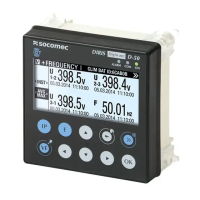
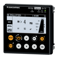
Specifications for ISOM D-15h and ISOM Digiware D-55/D-55h/D-75 displays.
Mechanical details of the display models.
Electrical ratings for the display units.
Communication capabilities of D-55 and D-55h displays.
Communication capabilities of the D-75 display.
Environmental operating conditions for displays.
Detailed performance classes for various parameters and sensors.
Performance classes related to power supply quality.
| Technology | Digital |
|---|---|
| Mounting | DIN rail |
| Protection Degree | IP20 |
| Communication protocol | Modbus RTU |
| Measurement Parameters | Voltage, Current, Power, Energy, Frequency, Power Factor |
| Current Measurement Range | 1A or 5A nominal (via CT) |
| Frequency Measurement Range | 45…65 Hz |
| Display | LCD |
| Operating Temperature | -25°C to +60°C |
| Storage Temperature | -40°C to +70°C |
| Relative Humidity | 95% RH non-condensing |
| Standards | IEC 61010-1 |
| Power Measurement Range | Depends on voltage and current range |