4.
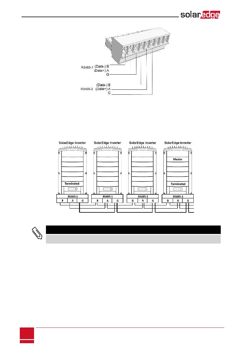
LoosenthescrewsofpinsA(+),B(-),andGontheleftoftheRS485terminalblock(RS485-1orRS485-2).
Figure 38: RS485 terminal block
5. InsertthewireendsintotheG, AandBpinsshownabove.UseFour-orsix-wiretwistedpaircablefor
thisconnection.YoucanuseanycolorwireforeachoftheA,BandGconnections,aslongasthe
samecolorwireisusedforallApins,thesamecolorforallBpinsandthesamecolorforallGpins.
6.
ForcreatinganRS485bus-connectallB,AandGpinsinallinverters.Thefollowingfigureshowsthis
connectionschema:
Figure 39: Connecting the inverters in a chain
NOTE
Do not cross-connect B, A and G wires.
7. Tightentheterminalblockscrews.
8. Checkthatthewiresarefullyinsertedandcannotbepulledouteasily.
9.
PushtheRS485terminalblockfirmlyallthewayintotheconnectorontherightsideofthe
communicationboard.
SolarEdge StorEdge Installation Guide MAN-01-000262-1.2
76
Creating an RS485 Bus Connection