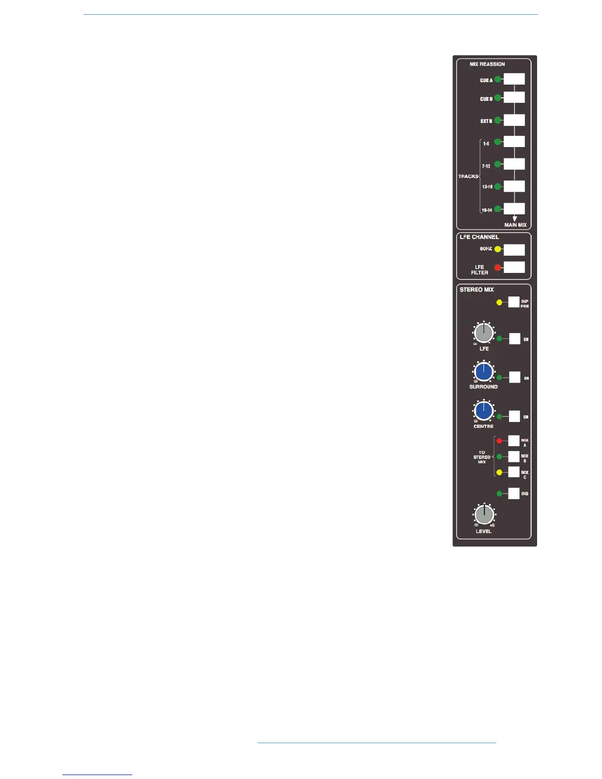
MMiixx RReeaassssiiggnn MMaattrriixx
This useful matrix, to the left of the main output compressor (see right), adds the selected
mix(es), post output level control, to the six Main Mix busses. Three stereo mixes — stereo
CUE A and CUE B, plus the output of the EXT B stereo monitor selector, can be
reassigned to Main Mix busses 1 and 2 (Mix A). The 24 Track busses are split into four groups
of 6, and are re-assigned in those groups to all of the Main Mix busses (busses 1 and 2 to
Mix A, 3 and 4 to Mix B, 5 and 6 to Mix C, etc.). This provides up to four 5.1 stems or four
triple stereo bus sets.
LFE Channel
This section (see right) enables a low pass filter to be switched (LFE FILTER) into the LFE
mix bus (Bus B Right) when working in surround. Two filter frequencies are provided — the
default 120Hz filter or, when the 80Hz button is pressed, a 80Hz option. The filter slope
is 12dB/Octave.
Stereo Mix Matrix
This matrix (see right) is used to sum the console’s Main Mix busses, with two exclusive
modes of operation.
Firstly, the three rotary controls and their associated ON buttons act as a 5.1 to Stereo
Downmix matrix to control the centre, surround and LFE contributions added to the
original 5.1 front L and R channels. By default, the downmix is sourced from the Main Mix
bus outputs, post processing and level control. INP PRE feeds the matrix directly from the
busses’ mix amps, thereby bypassing all processing.
The MIX A, B and C buttons are used to select a second mode of operation, which
provides a simple bus sum of the six Main Mix busses, when they are being used as three
stereo pairs or stems. The summing is post processing and level control. In both cases, the
resultant stereo mix has a master LEVEL trim and a separate pre level control insert point
(INS). The insert return supports the ‘Sum’ option, as found on the Bus Select Matrix
for Main Mix bus insert points. This mode is selected in the SSL/Misc/Setup menu,
selected via the centre section TFT screen (see Setup Menu).
22--3399
CCoonnssoollee OOppeerraattiioonnss
DDuuaalliittyy SSEE OOppeerraattoorr’’ss MMaannuuaall