SOLO BETA User Manual
Encoder Connection for BLDC, PMSM and ACIM motors (3-phase Motors):
For these types of Motors the connection is as below:
- The leading phase of the Motor in one specific rotational direction( in our case C.C.W
direction when the motor shaft is facing you) should be connected to output “A”, then the
next phase behind the leading phase to “B” and the last phase connected to output “C” of
SOLO.
-
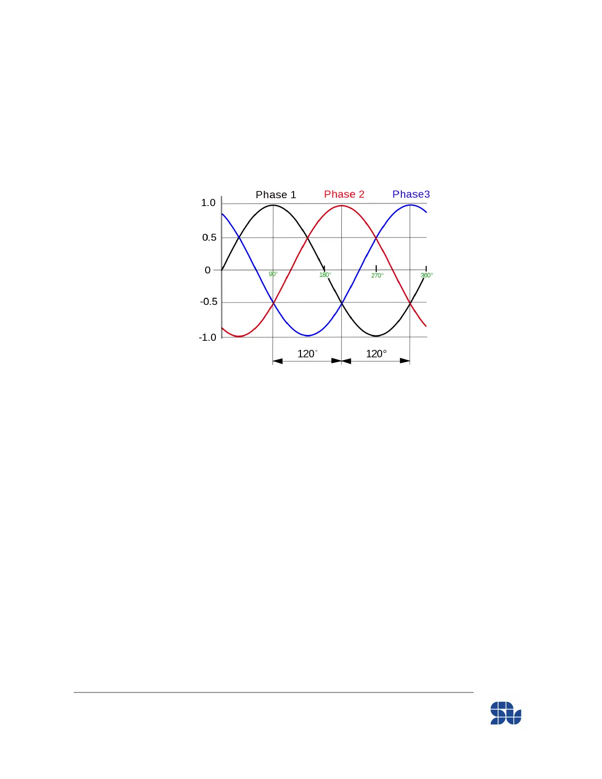
Figure 4 - Generic 3-phase motor output
As can be seen in Figure 4, the phase 3 in BLUE is leading the other two phases in one
specific direction, so in our case it should be connected to the output “A” of SOLO, and
then RED and Black are connected to output “B” and “C” respectively.
To find out the order of the phases in your 3-phase motor you can do:
1. Check the datasheet of Motors, it might be mentioned there(in C.C.W direction)
2. Connect the 3 wires of the motor to the Oscilloscope and try to turn the shaft in
the Counterclockwise direction while the shaft is facing you, then you should see
the order of phases on the screen as the BEMF voltage will appear. Connect the
Motor based on this order to the Motor outputs of SOLO as mentioned above and
record which pulse of Encoder Leads in this condition ( Pulse A or Pulse B )
- The Encoder Leading pulse relative to the leading phase connected to Motor output “A” of
SOLO, should be connected to input “Encoder_CHA” and the next pulse should be
connected to the “Encoder_CHB” inputs of the encoder connector.
www.solomotorcontrollers.com
January 2021 - Revision V_1.0.5 Copyright © 2020, All right Reversed. SOLO motor controllers.
27