SOLO BETA User Manual
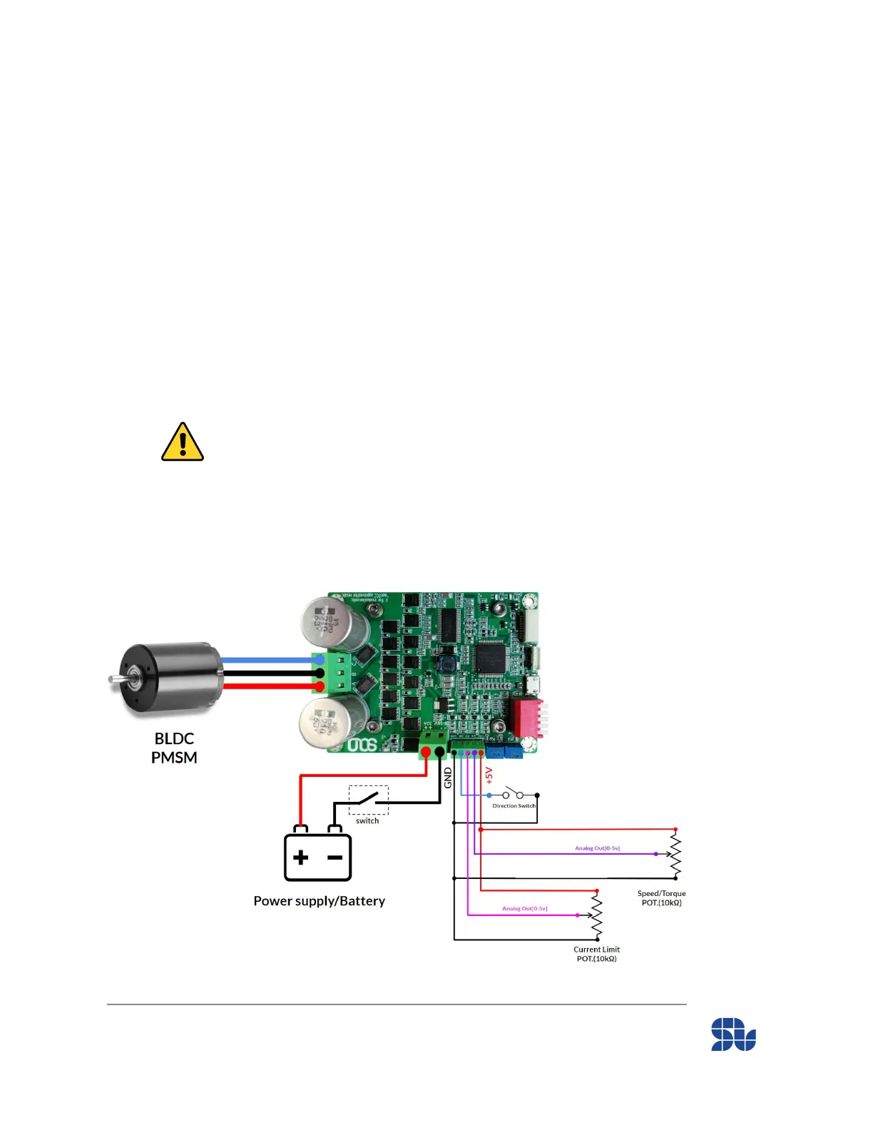
Standalone Wiring Example (No External Modules):
Here you can see an example of how to wire SOLO without having any external modules or special
settings, just by using a couple of potentiometers and a switch. In this example you can see a wiring
of a Brushless Motor in Closed-Loop Mode with Current Limit all done using only two
potentiometers. Please Not that:
- The current Limit Potentiometer is not mandatory to use, and if you leave the “P/F” input
open, the current Limit will be automatically set at 32A. This input in closed-loop mode
acts as if the voltage applied to this pin is 5V, it will stop the current floating to the motor(
Current Limit at zero), and if this pin is left open it will allow up to 32A floating into your
Motor, so any value between these will define the value of current limit.
The current Limit value = ((5.0 - Analogue Voltage applied at P/F input)/5.0) * 32
- The “DIR” pin is connected/disconnected To/From the Ground to alter the direction of rotation of
your Motor from C.W to C.C.W or reverse. Please notice that the high voltage level for this pin is
3.3V and it’s NOT 5V tolerant, if you like to connect the “DIR” to a 5V input, you MUST use a
resistor valued from 1kΩ to 2.2kΩ (only for this pin, the exact value is not important, but it must be
in this range), as can be seen in “Essential Wiring Example” in next parts.
www.solomotorcontrollers.com
January 2021 - Revision V_1.0.5 Copyright © 2020, All right Reversed. SOLO motor controllers.
38