SOLO BETA User Manual
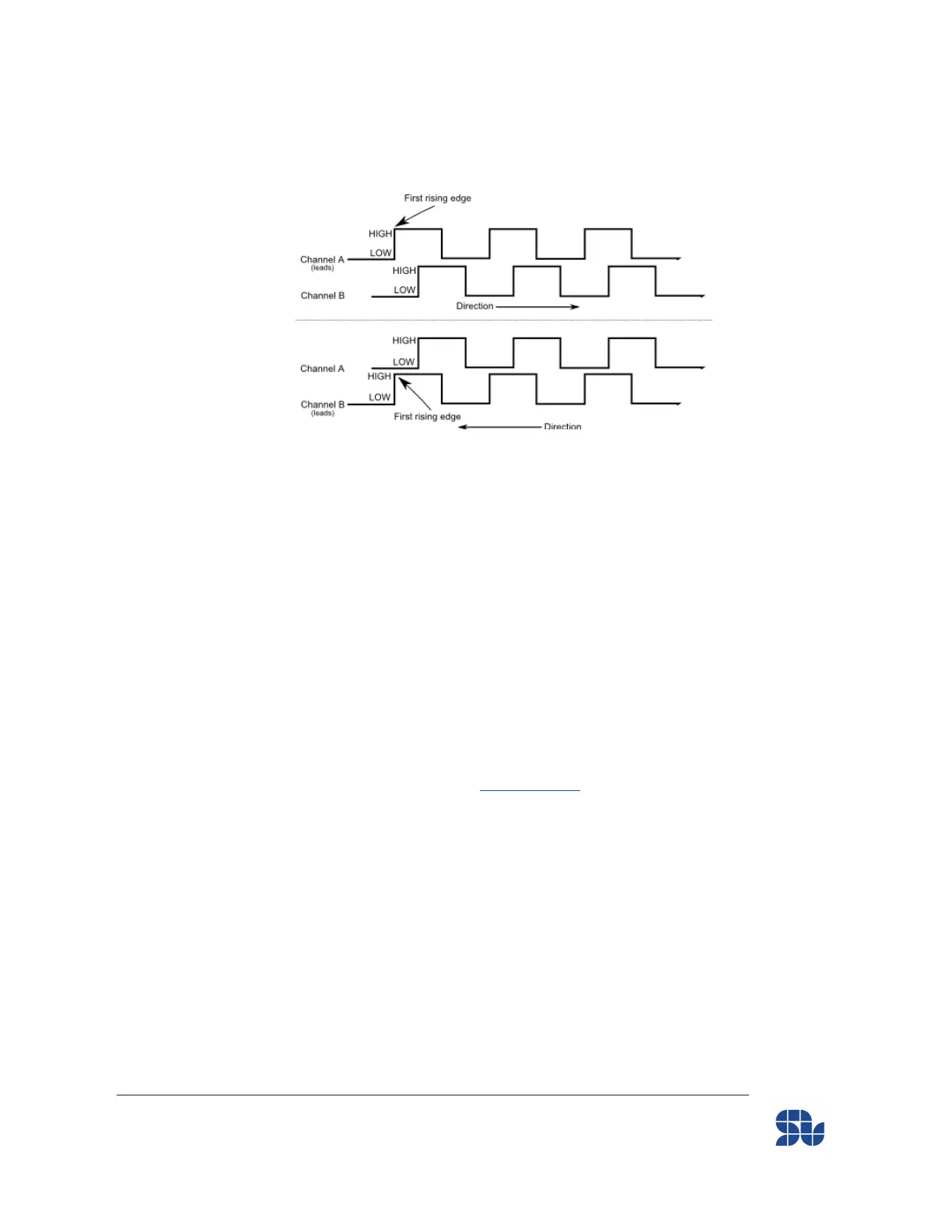
This means that while the Phase of the motor connected to output “A” leads the rest in
C.C.W. direction, the pulse going to “Encoder_CHA” is also leading the pulse going to
“Encoder_CHB” in encoder input.
Figure 5- Leading or Lagging pulses in Quadrature Encoders
Hall Sensor Connection for BLDC, PMSM and ACIM motors (3-phase Motors):
SOLO supports the possibility of controlling Speed or Torque of 3 phase motors using Hall
sensors, these types of sensors normally come with 3 wires as each of these wires are representing
a digital hall sensor output placed 120° apart and each of them are aligned to 1 phase of the motor.
There can be two other wires along-side with the Hall sensor outputs which are used for supplying
the Hall sensing circuitry. SOLO provides you a +5V and a Ground for this purpose. If you don’t
use the SOLO’s supply for the Hall sensors, make sure at least in one point there is a connection
between the Ground of SOLO to the Ground of Hall sensors output.
The connection of Motor’s wiring is similar to the Encoder part, so the Leading phase of the Motor
(the phase with leading BEMF) will be connected to “Motor Output 1”, and similarly for other two
motors’ phases.
To connect the Hall sensors output to SOLO, the wire that is associated to the phase of the Motor
that was connected to “Motor Output 1” of SOLO Before ( The phase with leading BEMF) should
be connected to “HALL_A” followed by connection of two other signals to “HALL_B” and
“HALL_C” based on their connection to Motor output pins. ( “HALL_B” should be connected to the
Hall signal output that is associated to Phase B of the Motor which lags Phase A but leads Phase C)
www.solomotorcontrollers.com
January 2021 - Revision V_1.0.5 Copyright © 2020, All right Reversed. SOLO motor controllers.
28