SOLO BETA User Manual
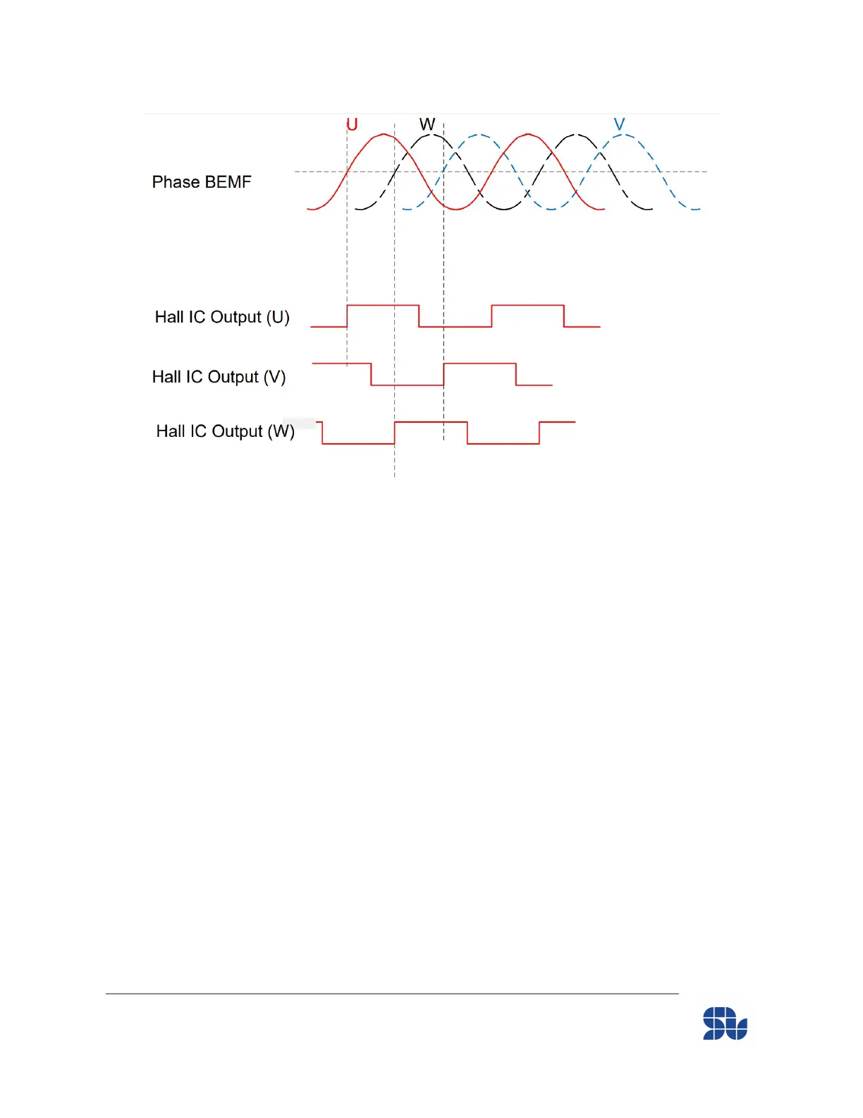
Figure 6- Three-Phase Hall sensors Output versus the Motor phases’ BEMF in C.C.W
Direction
If we suppose that while our Motor is rotating in C.C.W direction and we are having the Hall and
Motor BEM signals as in Figure 6, the Connection to SOLO will be :
Motor’s Connection :
● Wire “V” of the motor to “Motor Output 1” of SOLO
● Wire “W” of the motor to “Motor Output 2” of SOLO
● Wire “U” of the motor to “Motor Output 3” of SOLO
Hall Sensors Connection :
● Hall IC output (V) to “HALL_A”
● Hall IC output (W) to “HALL_B”
● Hall IC output (U) to “HALL_C”
www.solomotorcontrollers.com
January 2021 - Revision V_1.0.5 Copyright © 2020, All right Reversed. SOLO motor controllers.
29