MHC-V41D
7
CHECKING THE OPERATION AFTER REPAIR
After repair completion, connect the “iPhone/iPod”, “Walkman”,
“smartphone” etc. corresponding to this unit, and check the opera-
tion of playback, recording, charge, etc.
NOTE OF REPLACING THE ELECTRICAL PARTS ON
EACH BOARD FOR REPAIRING
Among mounted electrical parts on each board, only parts that are
described in the electrical parts list can be replaced for repairing.
The parts that are not described in the electrical parts list cannot be
replaced with single for repairing.
NOTE OF REPLACING THE MOTHER BOARD FOR
REPAIRING
Among mounted parts on the MOTHER board, only parts that are
described in the electrical parts list can be replaced for repairing.
When the parts that are not described in the electrical parts list are
defective, replace the complete mounted board.
In this service manual, the block diagram and printed wiring board
of the MOTHER board are described for reference.
Also, when the MOTHER board is replaced, be sure to refer to
“DESTINATION SETTING METHOD” and “NFC OPERATION
CHECKING METHOD” on page 6.
NOTE OF REPLACING THE PARTY LED, SW LED
NFC AND MS-476 BOARDS FOR REPAIRING
When the PARTY LED, SW LED, NFC and MS-476 boards are
defective, replace the complete mounted board or the whole parts
including the applicable board.
The mounted parts cannot be replaced with single for repairing.
In this service manual, the schematic diagram and printed wiring
board of the PARTY LED, SW LED, NFC and MS-476 boards are
not described.
Also, when the NFC board is replaced, be sure to refer to “NFC
OPERATION CHECKING METHOD” on page 6.
NOTE OF REPLACING THE SMPS BOARD FOR RE-
PAIRING
When the SMPS board is defective, replace the complete mounted
board.
The mounted parts cannot be replaced with single for repairing.
However, in this service manual, the block diagram, schematic dia-
gram and printed wiring board of the SMPS board are described
for reference.
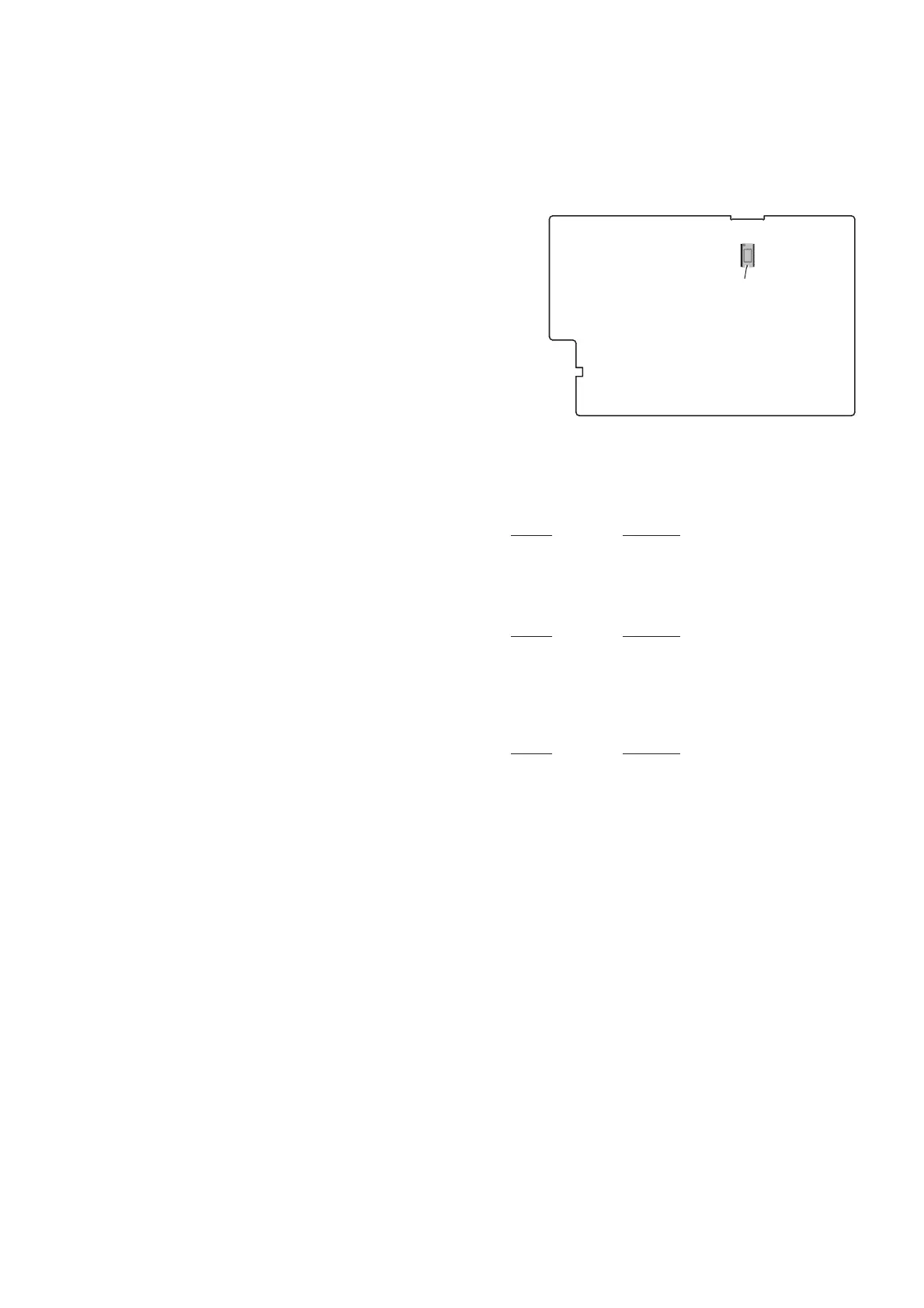
SPREADING OF COMPOUND
When the IC2002 on the MOTHER board is replaced, spread the
compound to the touching portion between the IC2002 and the
heat sink.
– MOTHER Board (Side A) –
IC2002
compound
TEST DISCS
Use following TEST DISC when this unit confi rms the operation
and checks it.
• For CD
Part No. Description
3-702-101-01 DISC (YEDS-18), TEST
4-225-203-01 DISC (PATD-012), TEST
J-2501-307-A DISC (HLX-A1), TEST
• For DVD SL (Single Layer)
Part No. Description
J-6090-069-A DISC (HLX-503), TEST (NTSC)
J-6090-088-A DISC (HLX-504), TEST (NTSC)
J-2501-305-A DISC (HLX-513), TEST (NTSC)
J-6090-077-A DISC (HLX-506), TEST (PAL)
• For DVD DL (Double Layer)
Part No. Description
J-6090-071-A DISC (HLX-501), TEST (NTSC)
J-6090-089-A DISC (HLX-505), TEST (NTSC)
J-2501-306-A DISC (HLX-514), TEST (NTSC)
J-6090-078-A DISC (HLX-507), TEST (PAL)
RELEASING THE DISC TRAY LOCK
The disc tray lock function for the antitheft of sample disc in the
shop is equipped.
It can release the lock function in the following procedure.
Releasing Procedure:
1. Press the [
1
] button to turn the power on.
2. Press the [FUNCTION] button to select the “DVD/CD” func-
tion.
3. Press two buttons of the [MEGA BASS] and [VOCAL FAD-
ER] simultaneously for 3 seconds.
4. The message “UNLOCKED” is displayed on the vacuum fl uo-
rescent display and the disc tray is unlocked.
Note: When “LOCKED” is displayed on the vacuum fl uorescent display,
the disc tray lock is not released by turning the power on/off with
the [
1
] button.

 Loading...