If your CD changer’s CQ~A~~ MODE
selector can be set to CD 1, CD 2, or CD 3,
be
sure fo set the command mocle to “CD 1”
and connect the changer to the CD jacks on
the receiver.
However, if you have a Sony CD changer
with VIDEO OUT jacks, set the command
mode to “CD 2” and connect the changer to
the VIDEO 2 jacks on the receiver.
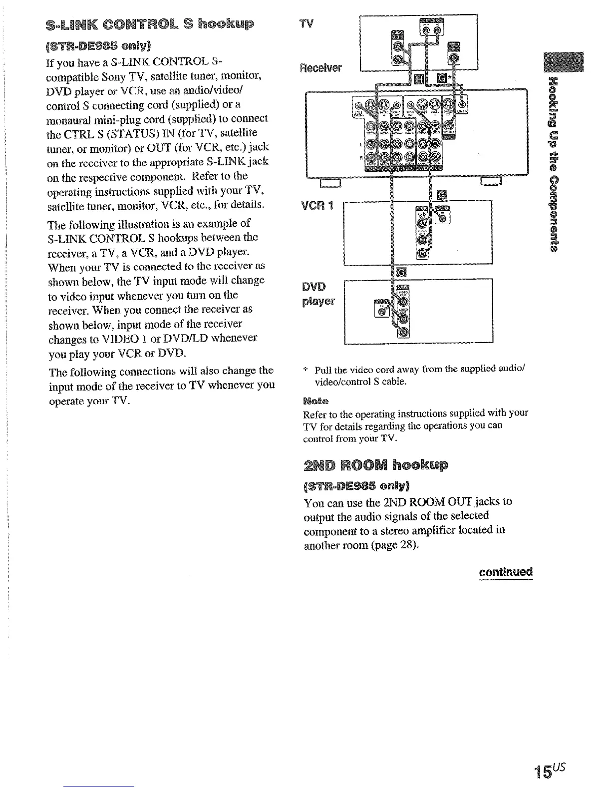
If you have a S-LINK CONTROL S-
compatible Sony TV, satellite tuner, monitor,
DVD player or VCR, use an audio/videol
control S connecting cord (supplied) or a
monaural mini-plug cord (supplied) to connect
the CTRL S (STATUS) IN (for TV, satellite
tuner, or monitor) or
OUT
(for VCR, etc.) jack
on the receiver to the appropriate S-LINK jack
on the respective component. Refer to the
operating instructions supplied with your TV,
satellite tuner, monitor, VCR, etc., for details.
The following illustration is an example of
S-LINK C~~TRQL S hookups between the
receiver, a TV, a VCR; and a DVD player.
When your TV is connected to the receiver as
shown below, the TV input mode will change
to video input whenever you turn on the
receiver. When you connect the receiver as
shown below, input mode of the receiver
changes to VIDEO 1 or ~VD~D whenever
you play your VCR or DVD.
The following connections will also change the
input mode of the receiver to TV whenever you
operate your TV.
* WI the video cord away from the supplied audio/
video/control S cable.
Refer to the operating instructions supplied with YOUI
TV for details regarding the operations you can
control from your TV.
You can use the 2ND ROOM OUT jacks to
output the audio signals of the selected
component
to a stereo amplifier located in
another room (page 28).