ioolc up the
components (pages 8-15).
White (L)
Red (R)
cS@j+ Yellow (video)
e White (L/audio)
Red (R/audio)
zcs@ZJ+ Yellow (video)
e Black
=llJKJP Orange
w Black
e Black (control S)
iny connections.
nections are completed.
:h the color-coded pins to the appropriate jacks on
audio) to white; and red (right, audio) to red.
5 plugs straight in until they click inlo place.
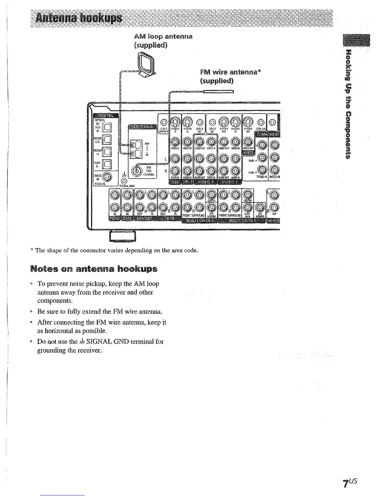
* The shape of the connector varies depending on the area code.
@ To prevent noise pickup, keep the AM loop
antenna away from the receiver and other
components.
* Be sure to fully extend the FM wire antenna.
* After connecting the FM wire antenna, keep it
as horizontal as possible.
3 Do not use the rh SIGNAL GND terminal for
grounding the receiver.