Performance Verification
VX4792 User Manual
F-27
This procedure checks the CLOCK OUTPUT signal amplitude.
Electrical Characteristic Checked: Auxiliary Outputs, Clock, Amplitude, on
page E–6.
Equipment Required: A 50 coaxial cable and an oscilloscope.
Prerequisites: The instrument must meet the prerequisites listed on page F–3.
Procedure:
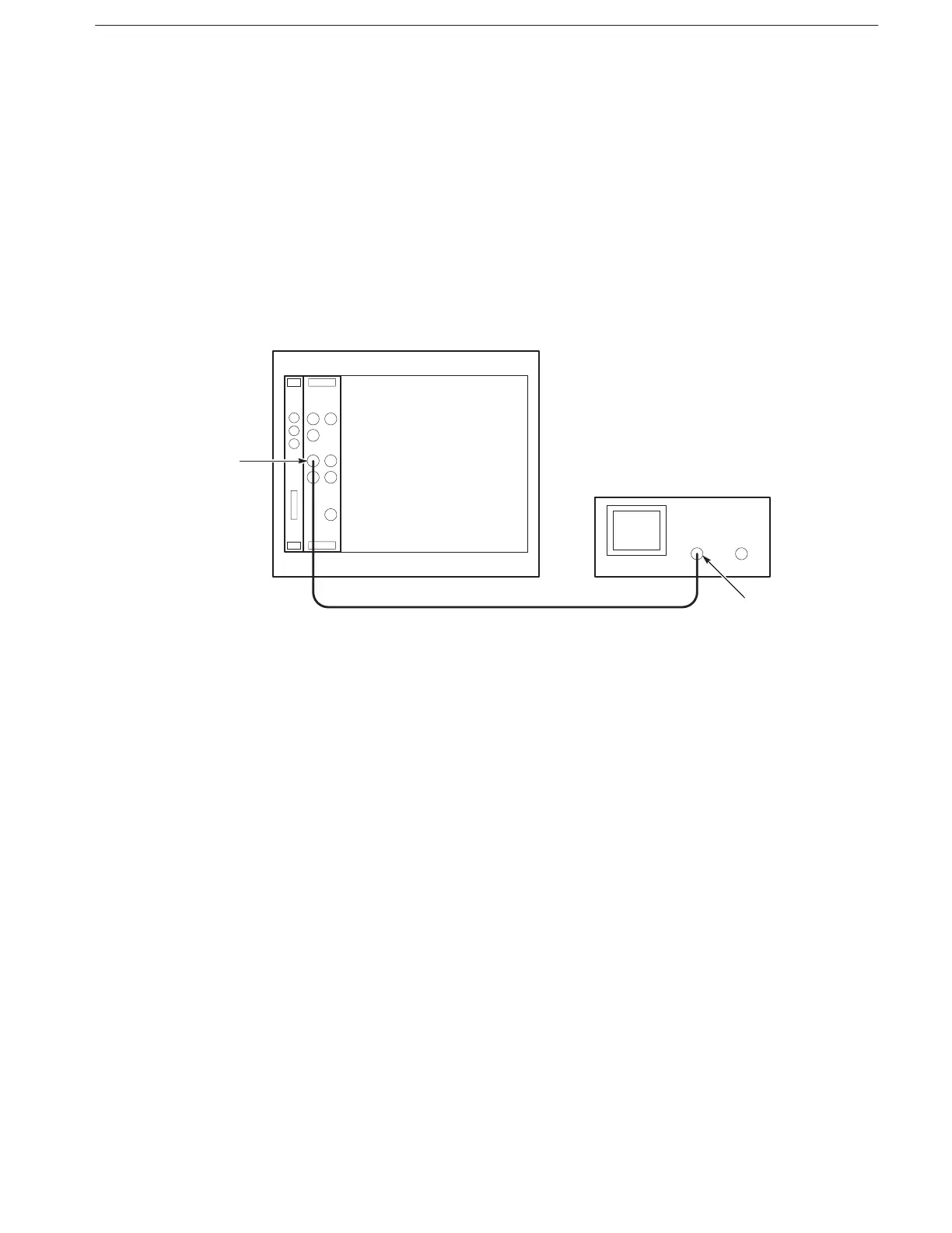
1. Install test setup and set test equipment controls (see Figure F–13):
Figure F-13: Clock Amplitude Initial Test Setup
a. Connect oscilloscope: Connect the CLOCK OUTPUT through a coaxial
cable to the oscilloscope CH1 vertical input.
b. Set oscilloscope controls:
Vertical CH1
Coupling DC
Scale 200 mV/div
Input impedance 50
Horizontal
Sweep 500 ns/div
Trigger
Source CH1
Coupling DC
Slope Positive
Level 500 mV
Mode Auto
Check Clock Amplitude