Functional Overview
2-16
VX4792 User Manual
The command (page 3–77) sets the polarity for the gate that
outputs the waveform or sequence with an external gate signal. Polarity may be
set to either positive or negative. When positive is selected, the waveform or
sequence is output while the level of the gate signal is higher than the gate
(trigger) level. When negative is selected, the waveform or sequence is output
while the level of the gate signal is lower than the set gate level.
The command (page 3–76) sets the trigger (gate) level for an
external trigger (gate) signal. The trigger (gate) level can be set in the range
–5.0 V to +5.0 V in steps of 0.1 V.
The command (page 3–74) sets the external trigger (gate)
source input impedance to either 50 or 1 M.
Waveform Timing
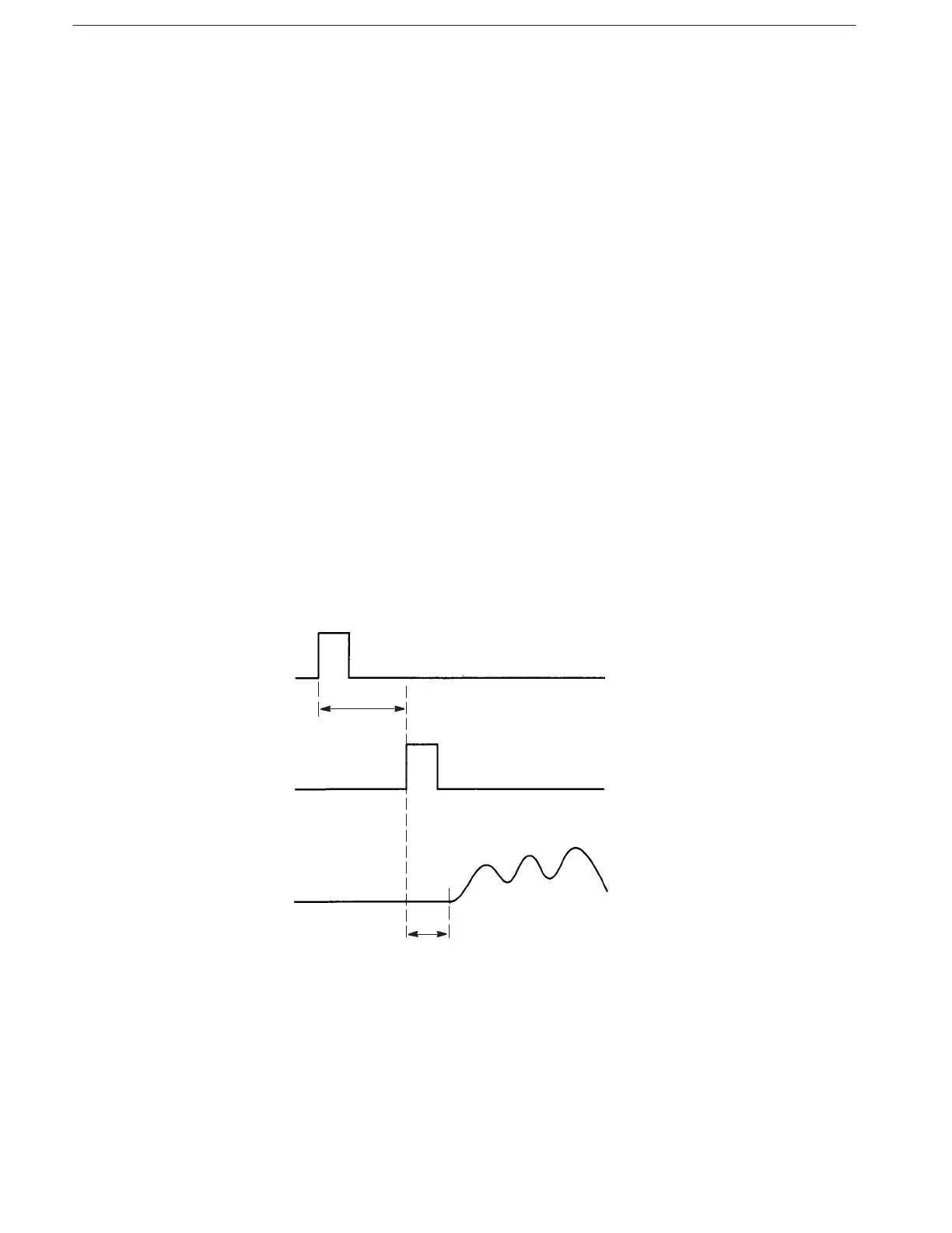
Figure 2–15 shows the timing relationship between the TRIGGER INPUT
signal, the SYNC OUTPUT signal, and the output waveform. Maximum delay
times are shown. Typical Sync→Signal Delay is 10 ns; typical Trigger→Signal
Delay is 50 ns.
The delay time increases when filters are used. See Table 2–3 on page 2–15 for
details.
Trigger Input
(Slope : Positive)
15 ns max
Sync Output (Start)
Waveform Output
(This delay changes if a
filter is inserted.)
100 ns max
Figure 2-15: Trigger Input, Sync Output, and Waveform Timing
Polarity (Gated Mode)
Level
Impedance