Functional Overview
2-14
VX4792 User Manual
Setting Output Filter
The waveform generator provides four filters for restricting the output frequency
bandwidth. The filter selections are 50 MHz, 20 MHz, 5 MHz, 1 MHz, and
Through (no filter). You can select a filter using the command
(page 3–41).
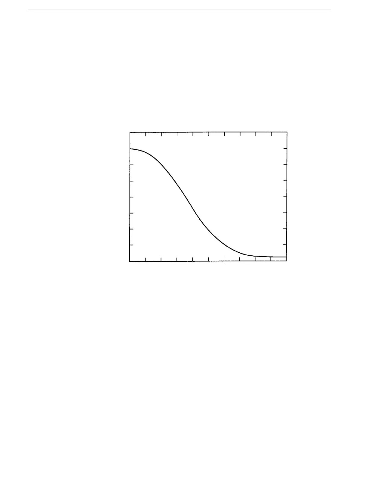
Filters within the waveform generator are low pass Bessel-type filters with soft
shoulder characteristics to avoid overshooting and ringing. The filter value
corresponds to the –3 dB cutoff point. Filter bandwidth is within 20% of the
value. Figure 2–13 shows a representative curve for the 1 MHz filter.
!
! "
Figure 2-13: Representative Filter Characteristics
The filters can be used to eliminate unwanted noise components of the wave-
form, and to reduce the fold-back component when there are a small number of
waveform points. The filters reduce the jaggedness of the waveform and raise the
S/N ratio. The rising and falling time for the waveform is approximately 4 ns
when a filter is not used.