Functional Overview
VX4792 User Manual
2-15
Time Delay Due to Filters
Each filter has a unique delay time. This delay affects the timing relationship
between the sync signal, marker signals, and waveform output signals. You can
reduce the delay by selecting a wider filter value. Table 2–3 shows the delay
relative to the sync and marker signals caused by the filters.
Table 2-3: Time Delay Caused By Filters
Filter Typical Time Delay
1 MHz 390 ns
5 MHz 78 ns
20 MHz 18 ns
50 MHz 11 ns
Setting Trigger Parameters for an External Trigger
The TRIGGER INPUT connector can receive external trigger (gate) signals with
a pulse width as narrow as 15 ns. You can use commands to set triggering
parameters including slope, polarity, level, and impedance. Each parameter is
described below.
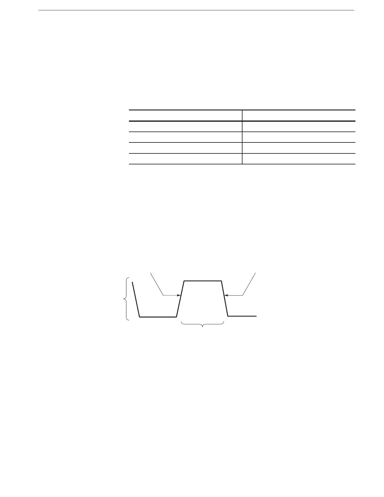
Figure 2–14 shows how the slope (polarity) and level controls relate to the
external trigger (gate) signal.
PositiveĆGoing Edge NegativeĆGoing Edge
Trigger Slope can be
positive or negative.
Trigger Level can
be adjusted
vertically.
Figure 2-14: Slope and Level Controls
The command (page 3–78) sets the slope for the external trigger
signal. Slope may be set to either positive or negative. When positive is selected,
the output is triggered at the rising edge of the external trigger signal. When
negative is selected, the output is triggered at the falling edge of the external
trigger signal.
Slope