Functional Overview
VX4792 User Manual
2-13
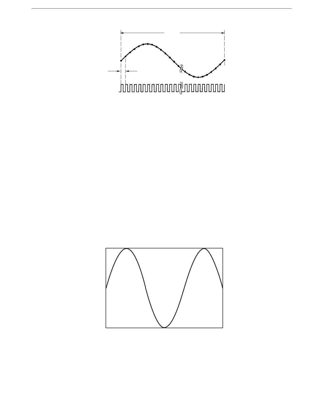
Figure 2-11: Clock and Waveform Points
The output waveform period (frequency) can be changed by selecting a new
clock frequency. For example, you may change the clock frequency to 10 MHz
(period of 0.1 ms) for the example in Figure 2–11. Now the total period for the
100-point waveform is 10 ms (0.1 ms multiplied by 100).
Setting Amplitude and Offset
The output amplitude and offset settings selected at power-on are 1 V and 0 V,
respectively. You can use the (page 3–22) and (page 3–59)
commands to select new output amplitude and offset values for the vertical axis
(12-bit full scale voltage). The output amplitude can be set in steps of 1 mV in
the range from 50 mV
p-p
to 5.000 V
p-p
. The output waveform offset can be set in
steps of 5 mV within the 2.5 V range.
Figure 2–12 shows an output waveform when the amplitude is set to 5 V and the
offset is set to +1 V.
Figure 2-12: Amplitude and Offset Setting